FIGURE 9-8. VALVE STEM AND
VALVE GUIDE INSPECTION
VT1020s
Springs: Check the valve springs for cracks, worn
ends, distortion and tension.
If
the spring ends are
worn, check the valve spring retainer for wear.
Check for spring distortion by placing each spring
on
a flat surface next to a square. Measure the
height of the spring and rotate it against the square
edge to measure its distortion. Check the spring
tension at the installed height in both the valve open
and closed positions, using a valve spring tester.
Replace any valve spring that is weak, cracked,
worn, or distorted.
Reconditioning Valves and Valve Seats
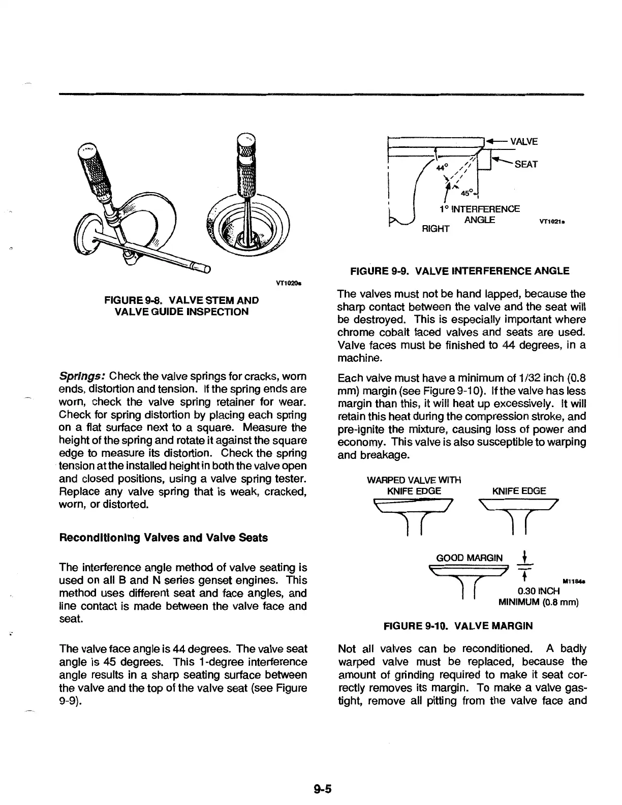
The interference angle method of valve seating is
used on all B and N series genset engines. This
method uses different seat and face angles, and
line contact is made between the valve face and
seat.
The valve face angle is
44
degrees. The valve seat
angle is 45 degrees. This 1-degree interference
angle results in a sharp seating surface between
the valve and the top of the valve seat (see Figure
9-9).
9-5
VT1021s
FIGURE 9-9. VALVE INTERFERENCE ANGLE
The valves must not be hand lapped, because the
sharp contact between the valve and the seat will
be destroyed. This is especially important where
chrome cobalt faced valves and seats are used.
Valve faces must be finished to 44 degrees, in a
machine.
Each valve must have a minimum of 1/32 inch (0.8
mm) margin (see Figure
9-1
0). If the valve has less
margin than this,
it will heat up excessively. It will
retain this heat during the compression stroke, and
pre-ignite the mixture, causing loss of power and
economy. This valve is also susceptible to warping
and breakage.
KNIFE EDGE
l (
\ 7
1 (
GOOD MARGIN
_!_
\ )
T
I(
111184a
0.301NCH
MINIMUM (0.8
mm)
FIGURE 9-10. VALVE MARGIN
Not all valves can be reconditioned. A badly
warped valve must be replaced, because the
amount of grinding required to make it seat cor-
rectly removes its margin. To make a valve gas-
tight, remove all pitting from the valve face and
 Loading...