TIMING
PSU
OR
MODEL
50
INJECTION
PUMPS
One of two methods can be used to determine the
proper timing button to time the fuel injection pump
correctly to the engine.
Method
1
Timing
by
Calculation
This procedure is used, when all dimensions are
available for replacing an old pump, before the pump
is installed. Timing by calculation requires the port
closing dimension and button thickness from the
pump being replaced.
It
also requires the port closing
dimension of the new pump. Put the dimensions in
the PORT CLOSING FORMULA, and calculate the
new button thickness. After determining the timing
button thickness, find the button code in Table
1.
If
injection pump is removed from the engine, make
sure the steel shims between pump and cylinder
block mounting remain the same. These shims main-
tain proper gear backlash.
Do
not change the pump mounting
LZx
shim’s total thickness or the proper
pump gear to camshaft gear mesh will be affected.
The shim’s thickness is established at the factory
during engine assembly and does not change unless
a new cylinder block is installed.
CAUT,ON
Port Closing Formula:
The formula for determining
the proper port closing (PC) timing button for a new
or replacement pump is as follows:
1.
Remove old pump.
2.
Determine port closing dimensions and original
button thickness from old pump.
A. Write down port closing dimension given on
old pump flange and port closing dimension
given on new pump flange. See example.
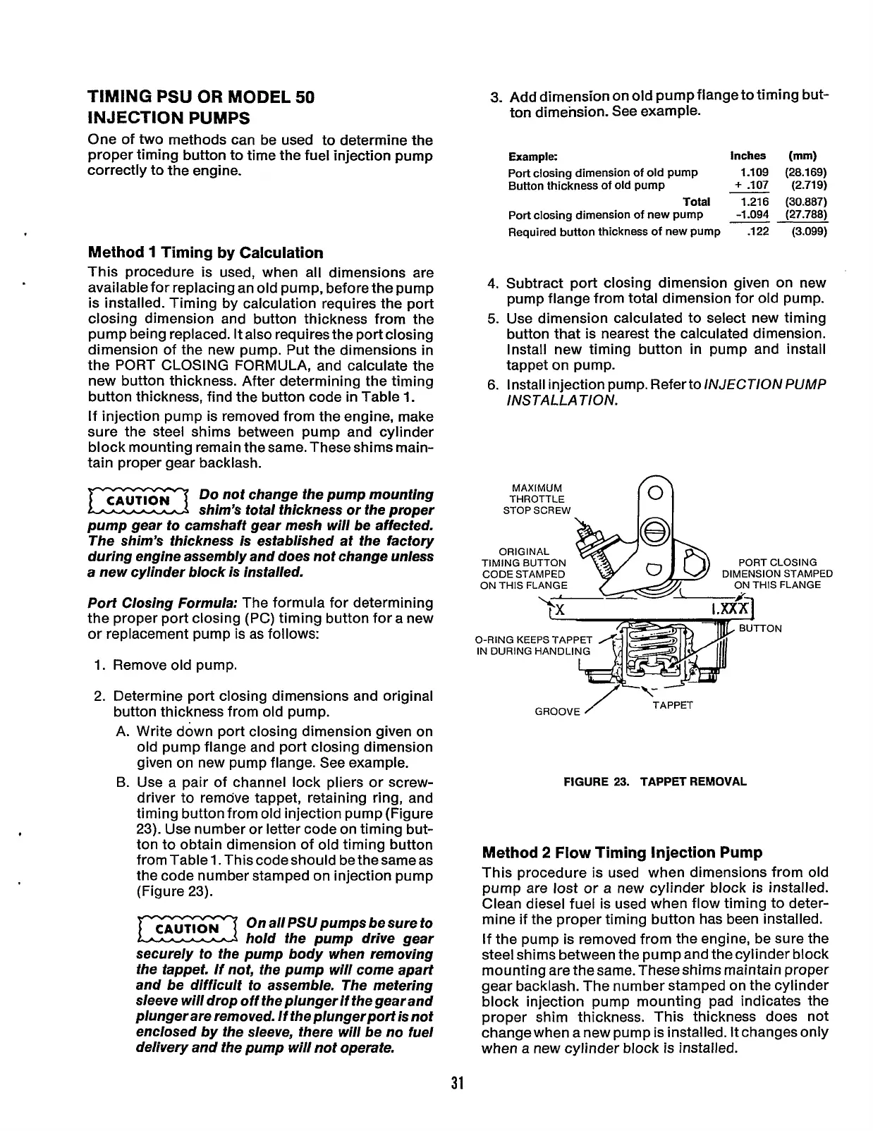
B.
Use a pair of channel lock pliers or screw-
driver to remove tappet, retaining ring, and
timing button from old injection pump (Figure
23).
Use number or letter code on timing but-
ton to obtain dimension of old timing button
from Table
1.
This code should be the same as
the code number stamped on injection pump
(Figure
23).
CAUT,ON
OnallPSUpumpsbesureto
rn
hold the pump drive gear
securely to the pump body when removing
the tappet.
If
not, the pump will come apart
and be difficult to assemble. The metering
sleeve will drop off the plunger if the gear and
plunger are removed. If the plungerport is not
enclosed by the sleeve, there will be no fuel
delivery and the pump will not operate.
3.
4.
5.
6.
Add dimension on
old
pump flange to timing but-
ton dimension. See example.
Example:
Inches
(mm)
Port
closing dimension
of
old pump 1.109 (28.169)
Button thickness
of
old
pump
+
-107 (2.719)
Total 1.216 (30.887)
Port
closing dimension
of
new pump -1.094 (27.788)
Required button thickness
of
new pump .122 (3.099)
Subtract port closing dimension given on new
pump flange from total dimension for old pump.
Use dimension calculated to select new timing
button that is nearest the calculated dimension.
Install new timing button in pump and install
tappet on pump.
Install injection pump. Refer to
lNJECT1ON
PUMP
INSTAL LA TION.
MAXIMUM
THROTTLE
STOP SCREW
II
CODE STAMPED
ON THIS FLANGE
O-RING KEEPS
IN DURING HA
----+
BUTTON
/
GROOVE
TAPPET
FIGURE
23.
TAPPET REMOVAL
Method
2
Flow
Timing Injection Pump
This procedure is used when dimensions from old
pump are lost or a new cylinder block is installed.
Clean diesel fuel is used when flow timing to deter-
mine if the proper timing button has been installed.
If the pump is removed from the engine, be sure the
steel shims between the pump and the cylinder block
mounting are the same. These shims maintain proper
gear backlash. The number stamped on the cylinder
block injection pump mounting pad indicates the
proper shim thickness. This thickness does not
change when a new pump is installed. It changes only
when a new cylinder block is installed.
31
Redistribution or publication of this document,
by any means, is strictly prohibited.