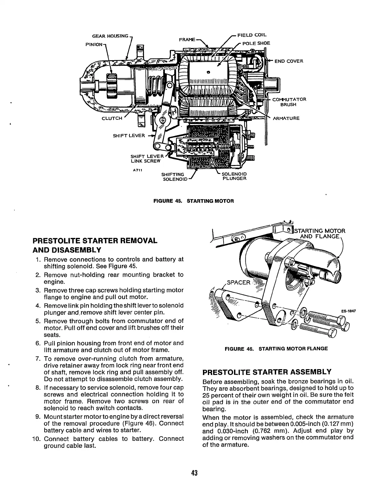
SHIFTING
/
SOLENOID
SOLENOID
PLUNGER
FIGURE
45.
STARTING
MOTOR
PRESTOLITE STARTER REMOVAL
AND
DISASEMBLY
1.
Remove connections to controls and battery at
shifting solenoid. See Figure
45.
2. Remove nut-holding rear mounting bracket to
engine.
3.
Remove three cap screws holding starting motor
flange to engine and pull out motor.
4.
Remove link
pin
holding the shift levertosolenoid
plunger and.remove shift lever center pin.
5.
Remove through bolts from commutator end of
motor. Pull off end cover and lift brushes off their
seats.
6. Pull pinion housing from front end of motor and
lift armature and clutch out of motor frame.
7.
To
remove over-running clutch from armature,
drive retainer away from lock ring near front end
of shaft, remove lock ring and pull assembly off.
Do
not attempt to disassemble clutch assembly.
8.
If necessary to service solenoid, remove four cap
screws and electrical connection holding
it
to
motor frame. Remove two screws on rear of
solenoid to reach switch contacts.
9.
Mount starter motor to engine by adirect reversal
of the removal procedure (Figure
46).
Connect
battery cable and wires to starter.
10.
Connect battery cables to battery. Connect
ground cable last.
FIGURE
46.
STARTING MOTOR FLANGE
PRESTOLITE STARTER ASSEMBLY
Before assembling, soak the bronze bearings in oil.
They are absorbent bearings, designed to hold up to
25 percent of their own weight in oil. Be sure the felt
oil
pad is
in
the outer end of the commutator end
bearing.
When the motor is assembled, check the armature
end play. It should be between 0.005-inch (0.127 mm)
and 0.030-inch (0.762 mm). Adjust end play by
adding or removing washers on the commutator end
of the armature.
43
Redistribution or publication of this document,
by any means, is strictly prohibited.