Do you have a question about the One for All SV-9453 and is the answer not in the manual?
Specifies the operational frequency range from 460 to 862 MHz and channel range from 21 to 69.
Details the antenna's gain of 10-12 dB and a front-to-back ratio of 28dB.
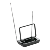
Provides the horizontal and vertical beam width (35-50° / 40-55°) and the antenna length of 760mm.
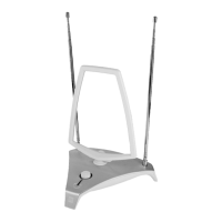
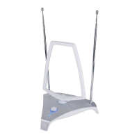
Illustrates the process of attaching antenna elements, showing connection points and fasteners.
Demonstrates how to adjust the angle or position of the antenna elements for optimal reception.
Shows the connection of the balun (signal transformer) to the antenna's feed point.
Details the procedure for mounting the assembled antenna onto a pole or mast.
| Cable length | 10 m |
|---|---|
| Connector(s) | F-Type & IEC coax |
| Maximum range | 40000 m |
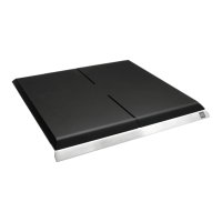
| Product color | Aluminum |
| Frequency range | 460 - 862 Mhz |
| Front to back ratio | 28 dB |
| Vertical beam width | 55 ° |
| Horizontal beam width | 50 ° |
| Antenna gain level (max) | 20 dBi |
| Digital signal format system | DVB-T |
| Quantity per pack | 1 pc(s) |
| Depth | 760 mm |
|---|