3User ManUal v1.6
Before you begin
Be up-to-date
Ensure you have the latest version of the manual, and
if not, download the errata sheet or the newest version at
onetesla.com/downloads.
Read the tutorials
All of our tutorials can be found at onetesla.com/tutorials
n Soldering tutorial
n De-soldering tutorial
n How a Tesla coil works
n Heat sink hardware installation
n Main board’s logic component installation
n Low voltage driver board test
n Main board’s power component installation
n IGBT installation
Observe good workspace practices
n Keep your workspace neat and orderly.
n Always obey common sense.
n Do not continue work if at any point you feel
uncomfortable with the hazards a challenging electronics
project poses.
n Use caution when soldering! Lead is hazardous, and
the iron is extremely hot.
Use the right equipment
Having the proper tools for electronic assembly, particularly a
powerful enough soldering iron, will make your life much easier!
Here are the tools you need to assemble your Tesla coil:
n temperature-controlled soldering iron, 40W minimum
n rosin-core solder of an appropriate thickness
n safety glasses
n small pliers
n ush cutters
n wire strippers
n small screwdriver
n hot glue gun
n multimeter
Optional but useful:
n packing tape
n masking tape
n solder wick or other desoldering tools
You will also need....
n spray-on or paint-on polyurethane varnish
n a mini USB cable to connect to the tinyTesla interrupter
n a laptop running 1T Panel or other MIDI control software
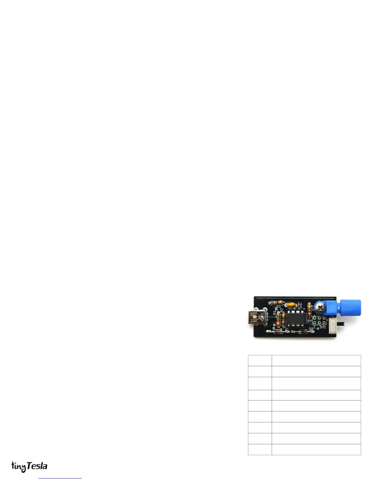
STEP 1: Assemble the interrupter
The interrupter is the Tesla coil’s music controller. It connects via a mini USB cable to a
computer, and appears as a MIDI device. Assemble it rst because you will need to use
it to ensure the low-voltage side of the main driver board is working. The interrupter is
also a small board with few parts, which—if soldered correctly—should work right away.
A. Install R1 through R4.
B. Install C1.
C. Install CN1, the mini USB connector.
D. Install zener diodes D1 and D2. Note that they are directional! Match the band
on the diode to the band on the board. Don’t confuse them with the 1N4148
signal diodes, which look the same except for their part number.
E. Install the socket of IC1. Do not solder the ATtiny directly to the board! Make
sure that the notch on the socket matches the notch on the board. Do not
solder the socket with the ATtiny inserted!
F. Insert the ATtiny into its socket, making sure that the dot on the chip is on the
same side as the notch on the socket.
G. Install IC2, the optical transmitter. Be careful! This component is delicate.
Secure it with a bolt and nut before soldering it in.
H. Install the slide switch.
Don’t worry, the ATtiny microcontroller in your kit is already programmed. If you ever
need to re-program your ATtiny, install a 6-pin header. Since your ATtiny comes
programmed, we didn’t include one.
R1
1.5kΩ (brown green red)
R2, R3
68Ω (blue grey black)
R4
100Ω (brown black brown)
C1 1uF (labeled 105)
CN1 mini USB connector
D1, D2 3.3V Zener Diodes
IC1 ATtiny and socket
IC2 optical transmitter
slide switch
 Loading...