7User ManUal v1.6
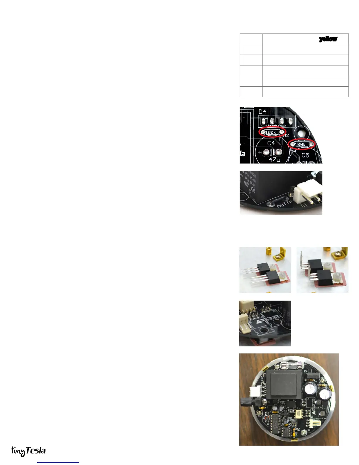
R2, R3 100kΩ (brown black yellow)
C4, C5
47uF electrolytic capacitors
X2
.1” right-angle header
D4
400V bridge rectier
110V jumper
F1
4A 250V fuse and clips
Step A
Step E
STEP 6: Install the Main Board’s
Power Components
Before you begin this step, you should add another layer of varnish to
the secondary!
In this step, install all the power components except for the IGBTs, which have a special
mounting procedure. To view a tutorial showing exactly how to do this, visit
http://onetesla.com/tutorials.
A. Install R2 and R3. It’s very important that you install these resistors! They are
bleeder resistors for the bus capacitors which drain their charge when you
power o the unit. Failure to install these will result in capacitors that can’t
drain their stored energy, and a board which is unsafe to service.
B. Install C4 and C5, the bus capacitors. Note the direction! There’s a white band
on the negative side, and positive is marked on the board.
C. Install X2, the .1” 3-pin right-angle header for the primary and antenna.
D. Install D4, the 400V bridge rectier.
E. If you are using a 110V kit you will need to install the 110V jumper next to the
line transformer. Take the 3-inch piece of solid-core AWG 22 wire and cut it to
size. Strip the ends and solder it in. If you are using a 220V kit DO NOT install
this jumper.
F. Install F1, the fuse clips and fuse. Clip the fuse into the clips to help them stay
in place while soldering.
STEP 7: Install the IGBTs
The IGBTs have a special mounting procedure. They are mounted ush against
the heat sink and soldered to the top of the board, not the bottom like the rest of
the components. To view a tutorial showing exactly how to do this, visit
http://onetesla.com/tutorials.
A. Ensure that the surface of the heat sink is clean. If there is any grease or
grime, clean it away using rubbing alcohol.
B. Using the outline in Appendix B as a guide, place the sil-pad on the heat sink.
Place the IGBTs on the sil-pad and use nylon screws to hold them in place.
C. Using pliers or your ngers, carefully bend the IGBTs 90 degrees at the point
where the legs become thinner.
D. Place the board over the IGBTs and position it so that the leads pass through
the holes in the board. This should be easy if you have the IGBTs rotated at the
correct angle, but can be tricky if they are not properly aligned.
E. Screw down the board into the standos, so that it is mechanically secure.
You may need to force the leads to bend a little bit to get the board to align to
the standos. You want everything mechanically secure before soldering, so
that you don’t put stress on the soldered joints.
F. Double-check that that your IGBTs are not touching each other, and that they
are not touching the heat sink. Tighten the nylon screws if needed.
G. Solder in the IGBTs on the top of the board. You may nd it easier to remove
the IGBTs later if you leave the leads long. In the case of a problem, the IGBTs
are usually the rst part to fail, so if you stress your coil it’s likely that you will be
replacing them!
Step B Step C
Step D
The completed board
 Loading...