9. Now we’re ready to connect all remaining parts. This is mostly a straight forward job,
and most parts can be directly connected with jumper wires, except maybe the
stepper motors. Some motors are delivered with pre-made plugs/connectors on both
ends, but others are not. However, in either case we probably need to extend these
cables so we have some room to move the mount in all directions (this is especially
important for the DEC Axis) relative to where we mount the OnStep Controller on our
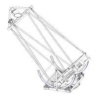
rigs. I used RJ45 Breakout Boards for this. This way I could simply connect or
disconnect the motors with standard network patching cables.
Figure 9 - OnStep Controller with RJ45 Connectors
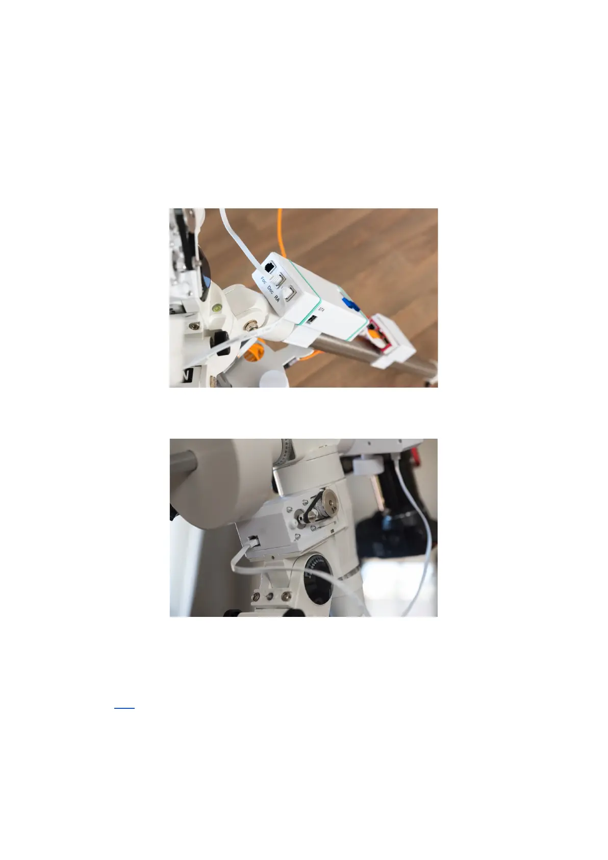
Figure 10 - Motor brackets with RJ45 Connectors
10. Now you can test the system with all motors connected (not necessarily to the
mount) and everything powered up. Verify full functionality by any of the possibilities
(Link) and observe how the motors are reacting. If any of the motors are going in the
wrong direction this can easily be rectified in the software; In Arduino IDE open the
onstep.ino file and in the Config.h file locate the “#define
AXISn_DRIVER_REVERSE” line (n is the affected axis 1,2,3 or 4) and set this to
“ON”. Save and re-flash the software to the Wemos R32. This axis should now move
in the opposite direction.
 Loading...