3A- 10 1973 OPEL SERVICE MANUAL
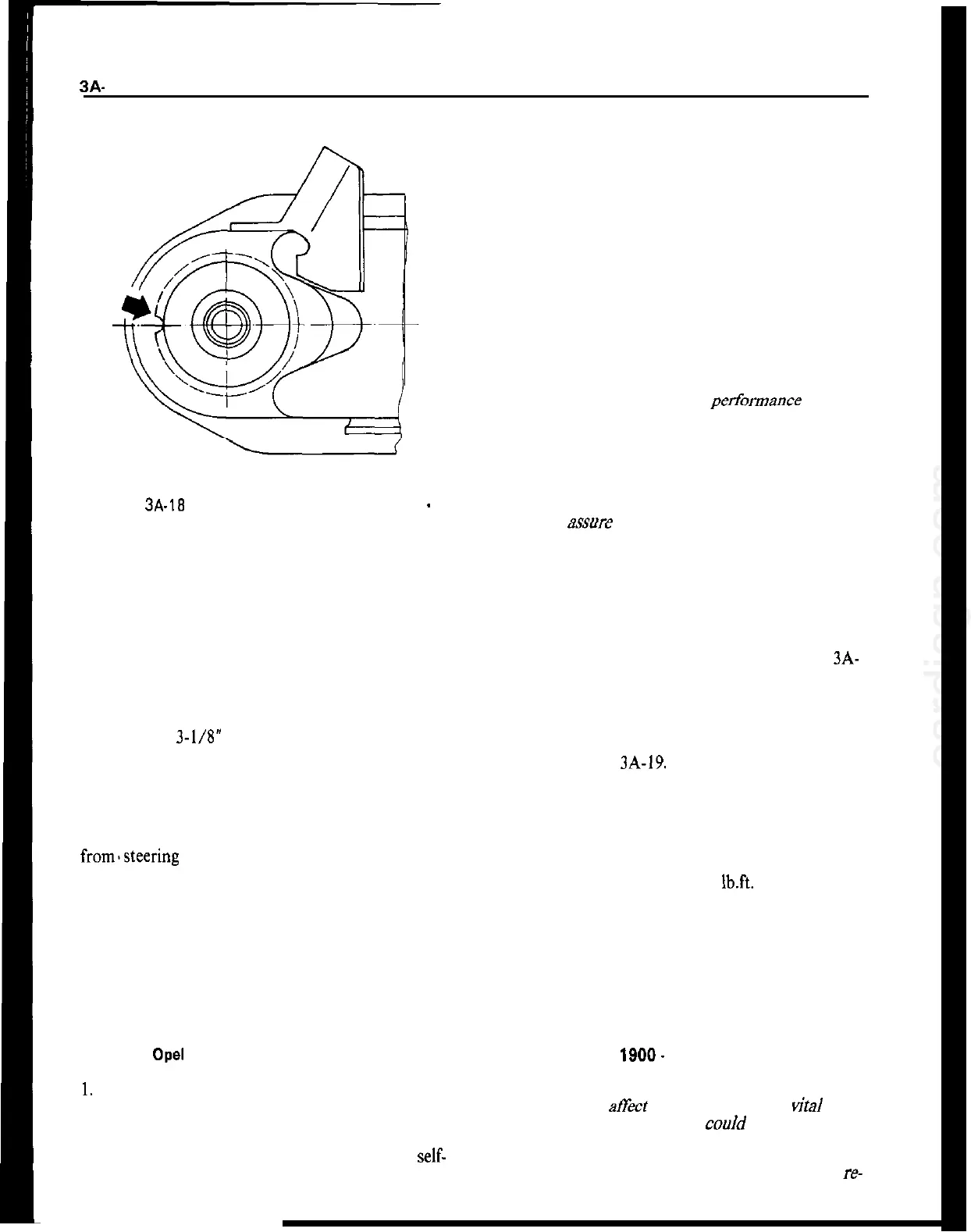
Figure 3A-18 Lower Ball Joint Notch Opel 1900
-
Manta
UPPER CONTROL ARM REMOVAL AND
INSTALLATION
Removal GT
1. Raise car and support at rear of front frame rails.
2. Remove front wheel.
3. Install spring compressor and compress spring
until there is 3-l/8” between compressor and lower
spring leaf.
4. Remove cotter pin and castle nut from upper ball
joint stud. Discard cotter pin.
5. Use tie rod remover J-21687 remove ball joint
from.steering knuckle. 6. Support brake drum to
relieve tension on brake hose.
7. Remove hex nut from upper control arm shaft.
Remove shaft and washers from shock absorber sup
port. Do not damage threads on control arm shaft.
8. Remove control arm from car. Do not lose inner
toothed washers. Note size and location of toothed
washers.
Removal
Opel
1900 . Manta
1,
Raise car and support at rear of front frame rails.
2. Remove front wheel
3. Unscrew upper control arm to cross member
self-
locking attaching nut.
4. Unscrew ball joint from upper control arm. Do not
turn upper control arm ball joint flange, as this
would result in a change of camber.
5. Support front wheel hub so that brake hose is not
stressed.
6. Pull out upper control shaft to cross member at-
taching bolt and remove control arm. Shims have to
be reinstalled in their original location to maintain
the proper caster setting.
Installation GT
CAUTION:
Fasteners are important attaching parts in
that they could affect the the perfonmmce of vital
components and systems, and/or could result in ma-
jor repair expense. They must be replaced with one
of the same part number or with an equivalent part
if replacement becomes necessary. Do not use a re-
placement part or lesser quality or substitute design.
Torque values must be used as specified during reas-
sembly to assure proper retention of these parts.
If rubber bushings on control arms are worn, arms
must be replaced.
1. Slide rubber rings over bushings. Slide rings over
inner sleeves of bushings. Place control arm in posi-
tion on shock absorber support, installing toothed
washers in their original positions. See Figure 3A-
19.
2. From front to rear, install control arm shaft. If
necessary, align washers and control arm bushings
with a small drift prior to installing control arm
shaft. See Figure
3A-19.
3. Tighten hex nut on control arm shaft finger tight.
4. Increase tension on spring compressor in order to
relieve tension on control arm shaft. Then torque hex
nut on control arm shaft to 33
Ib.ft.
5. Press ball joint stud into steering knuckle and
torque castle nut to 29 lb.ft. Install new cotter pin.
6. Remove spring compressor and lower car.
7. Check front end alignment.
Installation Opel
1900.
Manta
CAUTION:
Fasteners are important attaching parts in
that they could
at?&
the performance of vital com-
ponents and systems, and/or coo/d result in major
repair expense. They must be replaced with one of
the same part number or with equivalent parts, if
replacement becomes necessary. Do not use a re-
 Loading...