FRONT SUSPENSION
3A- 11
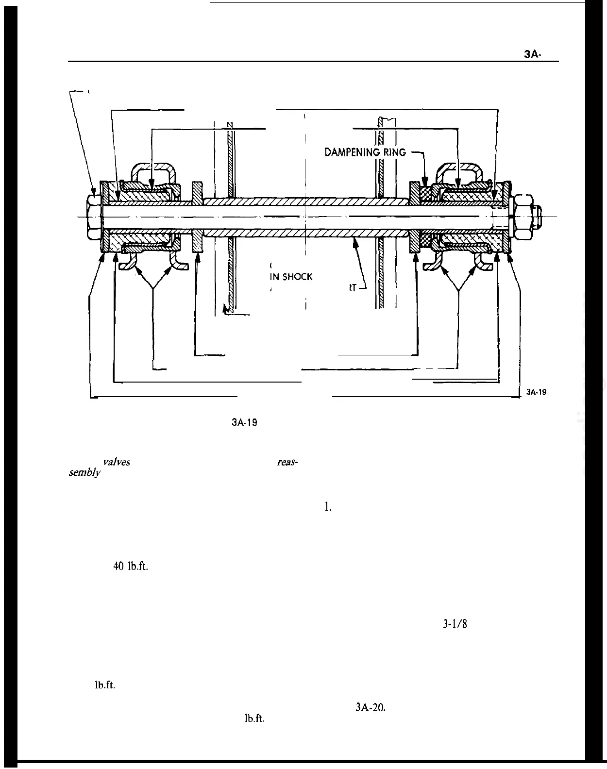
UPPER CONTROL ARM SHAFT
INNER SLEEVE
OUTER SLEEVE
RUBBER DAMPENIN
GUIDE SLEEVE
ABSORBER SUPPOR
SHOCK ABSORBER SUPPORT
ON FRONT SUSPENSION
CROSS MEMBER
-
TOOTHED WASHER
l-
UPPER CONTROL ARM
RUBBER BUSHINGS
PLATE WASHER
Figure
3A-19
Upper Control Arm Shaft and Bushings
placement part of lesser quality or substitute design.
Torque
valves
must be used as specified during
reas-
semb/y to assure proper retention of these parts.
1. On installation of the upper control arm, make
sure that damper bushing with the rubber shoulder
on both sides is always located in the rear.
2. Attach upper control arm to cross member and
torque to
40
lb.ft.
Always use new self-locking hex
nut. The upper control arm must be tightened in
horizontal position only. This applies also to all other
attaching joints in connection with rubber damper
bushings in the control arms of the front suspension
so that the rubber parts under load are in an almost
twist-free condition. This position exists, if the hooks
J-23697 are used.
3. Attach ball joint to upper control arm and torque
to 29
lb.ft.
4. Install wheel and torque nuts to 65
lb.ft.
Lower
car.
LOWER CONTROL ARM REMOVAL AND
INSTALLATION
Removal GT
1.
Raise car and support at rear of front frame rails.
2. Remove front wheel.
3. Remove cotter pin from castle nut on ball joint
stud and back off castle nut two (2) turns. Hit ball
stud a sharp blow to break it loose. DO NOT
REMOVE NUT.
4. Install spring compressor (J-21689) and compress
spring until a distance of
3-l/8
inches is achieved
between spring compressor and lower spring leaf.
5. Disconnect and compress shock absorber.
6. Support rail of spring compressor with a jack.
Remove lower control arm from frame cross mem-
ber. Nuts may have to be removed with a punch. See
Figure 3A-20. Discard the lock nuts.
7. Remove lower ball joint stud nut. Slightly lower