3A- 12 1973 OPEL SERVICE MANUAL
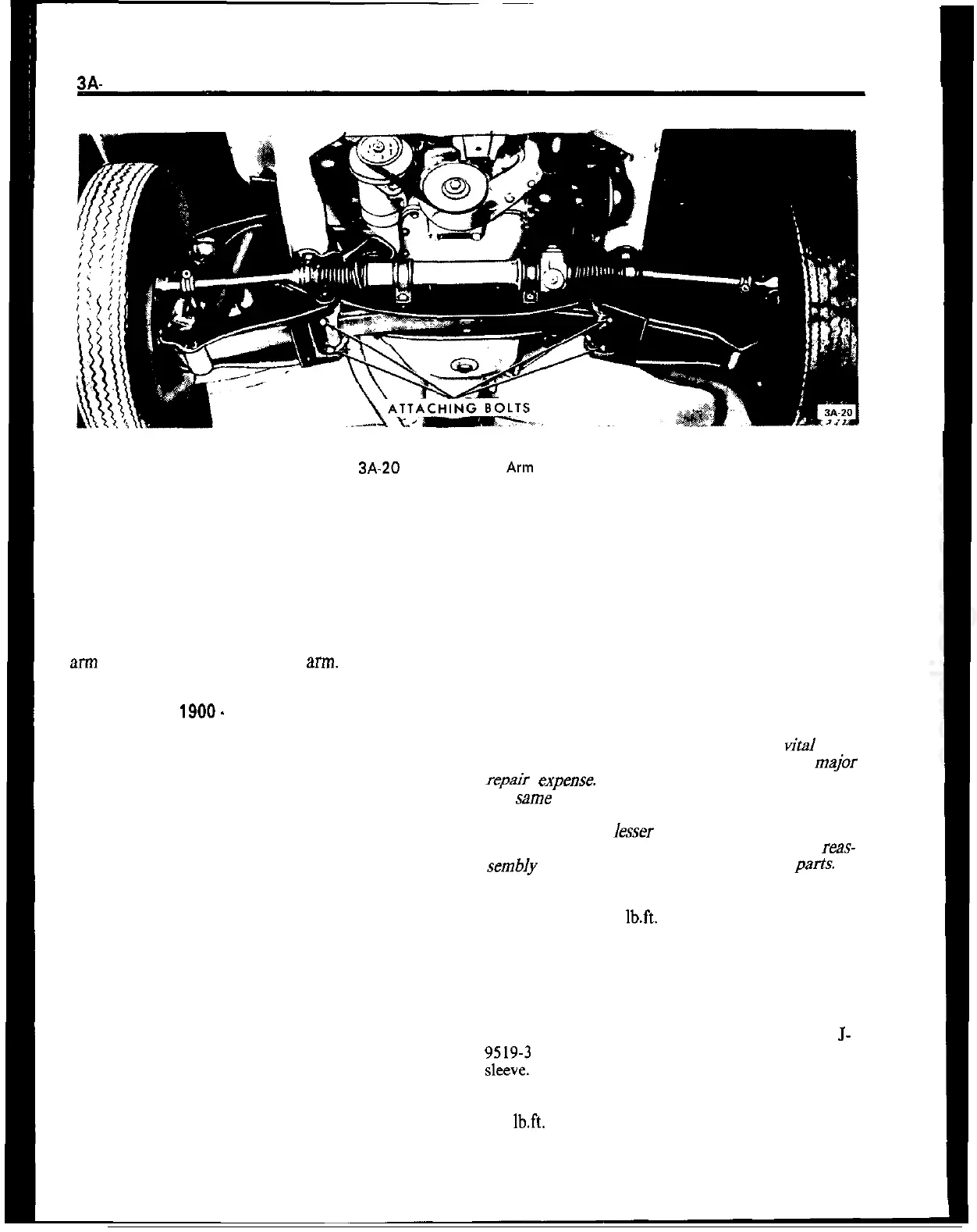
Figure 3A-20 Lower Control
Arln
Attachment
jack so that spring and lower control arm assembly
is removed from the front cross member and steering
knuckle.
8. Lower jack, spring compressor, and front spring
with control arm assembly. Remove lower control
arm to spring nuts.
9. Release spring compressor and remove control
arm attaching bolts and control aRn.
Removal Opel
1900.
Manta
1. Prior to raising car, install upper control arm
hooks J-23697.
2. Raise car and support with stands. Hoist should
be left in the raised position to maintain pressure on
lower control arm.
3. Remove front wheel.
4. Detach both stabilizer supports from cross mem-
ber to body support.
5. In lower control arm, remove self-locking hex
head bolt from stabilizer support and remove
washer.
6. Using a pry bar, pry stabilizer bar out of lower
control arm support.
7. Remove shock absorber.
8. At lower control arm ball joint, remove castle nut
cotter pin and remove nut.
9. With suitable drift, detach lower control arm ball
joint from steering knuckle.
10. Loosen nut that retains lower control to front
cross member.
11. Slowly lower hoist to release spring tension.
12. Swing lower control arm downwards and remove
front spring.
13. Remove nut that retains lower control arm to
front cross member and remove lower control arm.
Installation GT
CAUTION:
Fasteners are important attaching parts in
that they could affect the performance of
vital
com-
ponents and systems, and/or could result in major
repair expeme. They must be replaced with one of
the same part number or with an equivalent part if
replacement becomes necessary. Do not use a re-
placement part of lesser quality or substitute design.
Torque values must be used as specified during
reas-
sembly to assure proper retention of these parts
1. Attach lower control arm to front spring eye.
Torque bolts to 18
1b.R.
2. Install spring compressor and with a jack raise
spring compressor with spring and control arm as-
sembly into position for pressing ball joint into steer-
ing knuckle.
3. Press ball joint into steering knuckle. Use
J-
;lYN;: as installer and J-21690 as a supporting
4. Install castle nut on ball joint stud and torque to
54
lb.ft.
Install new cotter pin.
5. Attach lower control arm to frame cross member
using new lock nuts.