3A. 14 1973 OPEL
SERVkE
MANUAL
Figure 3A-22 Caliper Removed and Hung by Wire
steering knuckle. Swing steering arm and tie rod to
the side.
7. Remove castle nut cotter pin, unscrew nut and
pull steering knuckle off lower control arm ball joint.
Installation GT
CAUTION: Fasteners are important attachingparts in
that they could affect the performance of
viral
com-
ponents and systems, and/or could result in major
repair expense. They must be replaced with one of
the same part number or with an equivalent part if
replacement becomes necessary. Do not use a re-
placement part of lesser quality or substitute
desig.
Torque values must be used as specified during reas-
sembly to assure proper retention of these parts.
1. Always replace paper gasket when installing dust
shield on steering knuckle. Lightly coat both surfaces
of paper gasket with chassis lubricant before installa-
tion and torque attaching bolts to 47
lb.ft.
2. Install lower ball joint in steering knuckle. Torque
castle nut to 54
Ib.ft.
Install new cotter pin.
3. Attach shock absorber at lower end. Torque bolts
to 30 lbs. ft.
4. Install upper ball joint. Torque castle nut to 29
lb.ft.
Install new cotter pin.
5. Remove spring compressor.
6. Install hub and disc on spindle and tighten spindle
nut as stated under MAINTENANCE AND AD-
JUSTMENTS in this section.
7. Install caliper on steering knuckle and torque bolts
to 72
lb.ft.
See Figure
3A-21.
8. Install wheel and torque wheel nuts to 65
lb.ft.
Installation Opel 1900
-
Manta
CAUTION: Fasteners are important attachingparts in
that they could
affit
the performance of vital com-
ponents and systems, and/or could result in
ma&
repair expense. They must be replaced with one of
the same part number or with equivalent parts, if
repfacement becomes necessary. Do not use a re-
placement part of lesser quality or substitute design.
Torque values must be used as specified during reas-
sembly to assure proper retention of these parts.
1. Attach steering knuckle to lower control arm ball
joint. Torque castle nut to 54
lb.ft.
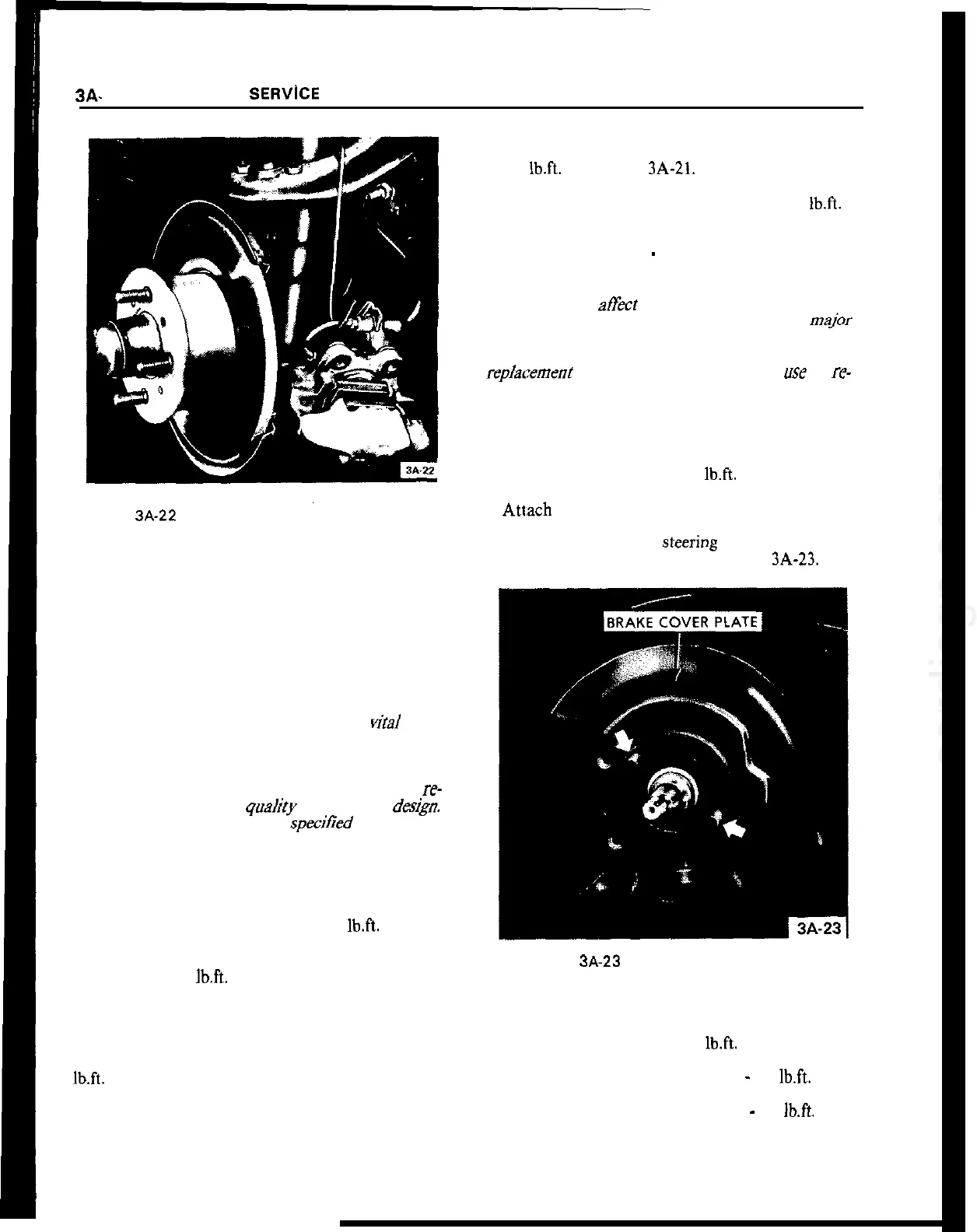
2. Atl,ach brake cover plate and steering arm to steer-
ing knuckle. If required, install new paper gasket
between cover plate and steering knuckle. Care for
proper seat of T-head bolts. See Figure
3A-23.
Figure 3A-23 Attaching Brake Cover Plate
3. Install front wheel hub and brake caliper.
4. Attach steering knuckle to upper control arm ball
joint. Torque castle nut to 40
lb.ft.
5. Steering arm to steering knuckle
_
58
lb.ft.
6. Brake caliper to steering knuckle
-
72
lb.ft.
7. Adjust front wheel bearing clearance.
8. Remove stands and lower car
 Loading...