STEERING LINKAGE
38.19
STEERING LINKAGE
CONTENTS
Subject
DESCRIPTION AND OPERATION:
Description
and
Operation of Tie
Rods
. . . . . . . . . . . . . . . . . . . . . .
DIAGNOSIS: (Not Applicable)
MAINTENANCE AND ADJUSTMENTS: (Not
Applicable)
MAJOR REPAIR:
Removal and
Installation of
Tie Rods
. . . . . . . . . . . . . . . . . . . . . . . .
Disassembly
and Reassembly
of
Tie
Rods
. . . . . . . . . . . . . . . .
SPECIFICATIONS:
Tightening Specifications ..,.............................................
Page No.
38-19
3B-19
38-21
jB-21
DESCRIPTION AND OPERATION
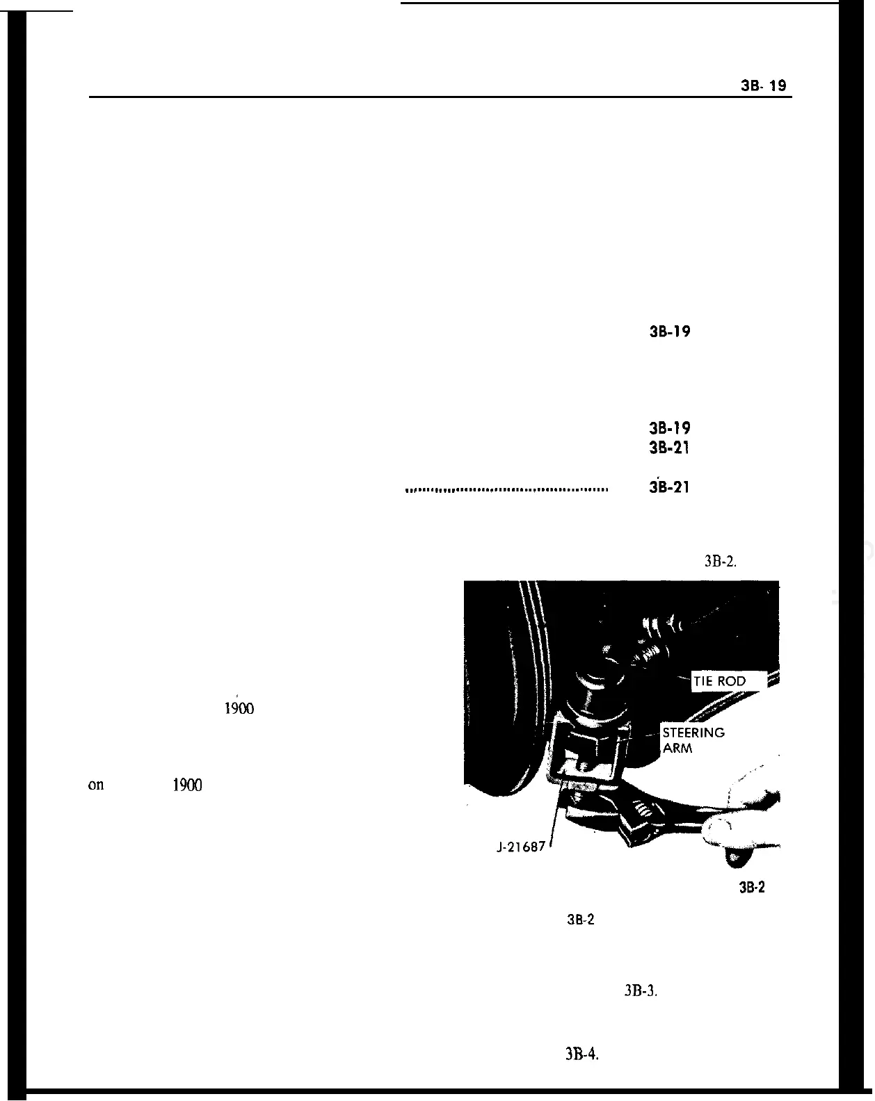
2. Using remover J-21687, pull outer tie rod ball
studs out of steering arms. See Figure
3B-2.
DESCRIPTION AND OPERATION OF TIE RODS
Tie rods on the GT are connected to both rack ends
by means of a ball joint. Two rubber bellows between
ball joint and steering gear housing protect rack and
ball joints against dirt, dust and mud. The ball joints
of the tie rods do not require service.
Tie rods on the Opel l&O and Manta are connected
to both rack ends by means of a axial joint. Two
rubber bellows between the axial joint and steering
gear housing protect the rack and axial joints against
dirt, dust, and mud. The ball joint of the tie rod ends
on
the Opel
1900
and Manta are maintenance free
and must not be disassembled.
MAJOR REPAIR
REMOVAL AND INSTALLATION OF TIE RODS
38-2
Removal
Figure
38-2
Removing Ball Stud
In order to avoid the possibility of dirt entering the
steering gear assembly via the rack, it is recom-
mended that rods and area immediately surrounding
the gear assembly be wiped free of loose dirt prior to
removal.
3. Remove clamp securing one end of rubber bellows
to tie rods and slip bellows off tie rods to expose nut
or lock plates. See Figure
3B-3.
1. Remove cotter pins securing nuts on tie rod ends
and remove nuts. Discard cotter pins.
4. On the GT, bend up round edges of lock plate
from tie rod ball studs and unscrew ball studs From
rack. See Figure
3B-4.