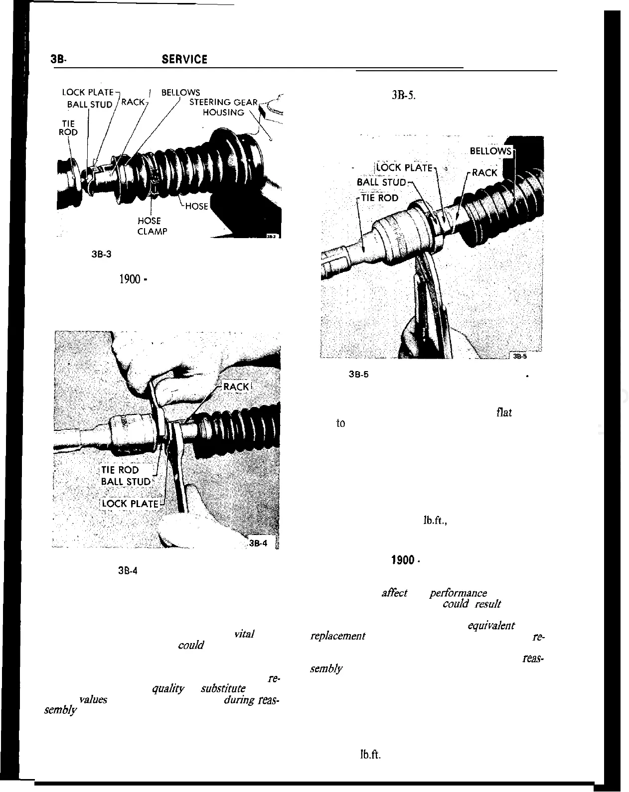
Figure 38-3 Bellows Removed From Tie Rod GT
5. On the Opel
1900
-
Manta, unscrew tie rod from
axial joint. It is important that rack be held secure
with open end wrench to prevent damage to rack
teeth.
38.
20 1973 OPEL SERWCE MANUAL
Figure 38.4 Removing Tie Rods. GT
Installation . GT
CAUTION:
Fasteners are important attaching parts in
that they could affect the performance of
vital
com-
ponents and systems, and/or coo/d result in major
repair expense. They must be replaced with one of
the same part number or with an equivalent part if
replacement becomes necessary. Do not use a re-
placement part or lesser
quaJity
or sub.Mute design.
Torque
vaJues
must be used as specified
during
reas-
sembJy
to assure proper retention of these parts.
1. Install new lock plates onto tie rod ball studs and
screw ball studs into rack while holding bent tab of
lock plates against flat on rack. Torque ball studs 43
lb.ft. See Figure
3B-5.
It is important that rack be
held secure with open end wrench to prevent damage
to rack teeth.
Figure 38-5 Bending Lock Plate Over Ball Stud
-
GT
2. Bend round edges of lock plate over
flat
on ball
stud
‘to
lock ball stud in position.
3. Position rubber bellows and hose clamps over tie
rods and adjust clamp so that wire ends are pointing
in same direction as adjusting screw. Check that bel-
lows are not twisted and will compress and expand
properly.
4. Connect outer tie rod ball stud to steering arm,
torque castle nut to 29
lb.ft.,
and lock in position
with new cotter pin.
Installation Opel
1900.
Manta
CAUTION:
Fasteners are important attachingparts in
that they could
ah%
the
performance
of vital com-
ponents and systems, and/or
couJd
reslllt
in major
repair expense. They must be replaced with one of
the same part number or with an
equivalenr
part if
repJacement
becomes necessary. Do not use a re-
placement part of lesser quality or substitute design.
Torque valves must be used as specified during reas-
sembfy to assure proper retention of these parts.
1. Screw tie rod into axial joint.
2. Attach tie rod end to steering arm and torque nut
to 29 lb.ft. Install new cotter pin.
3. Adjust toe-in and then torque lock nut of both tie
rods to 47 lbft.