3E- 38
,1973
OPEL SERVICE MANUAL
ponents and systems, and/or could result in major
repair expense. They must be replaced with one or
the same part number or with
an
equivalent part if
replacement becomes necessary. Do not use a
re-
placement part of lesser quality or substitute design.
Torque
values
must be used as specified
during
reas-
sembly to assure proper retention of these parts.
On installation, make sure steering wheel spokes
point downwards and steering gear is in high point.
1. Carefully insert steering mast into universal joint
flange.
2. Loosely attach slide-off base attaching nuts at un-
derside of instrument panel.
3. Attach steering mast jacket at front of dash, using
a notched hex nut.
4. Torque nuts at slide-off base to II
lb.ft.
5. Tighten screw at steering mast clamp to 22
lb.ft.
6. Reconnect wires to directional signal switch and
ignition switch.
7. Reconnect battery.
REMOVAL AND INSTALLATION OF
STEERING WHEEL
This procedure may be performed with the steering
column assembly either removed or installed in the
car.
Removal
1.
Disconnect battery.
2. Pry off horn cap and remove wires from cap. See
Figure
3E-3.
3. Bend lockplate tabs down and take off steering
shaft nut and lockplate.
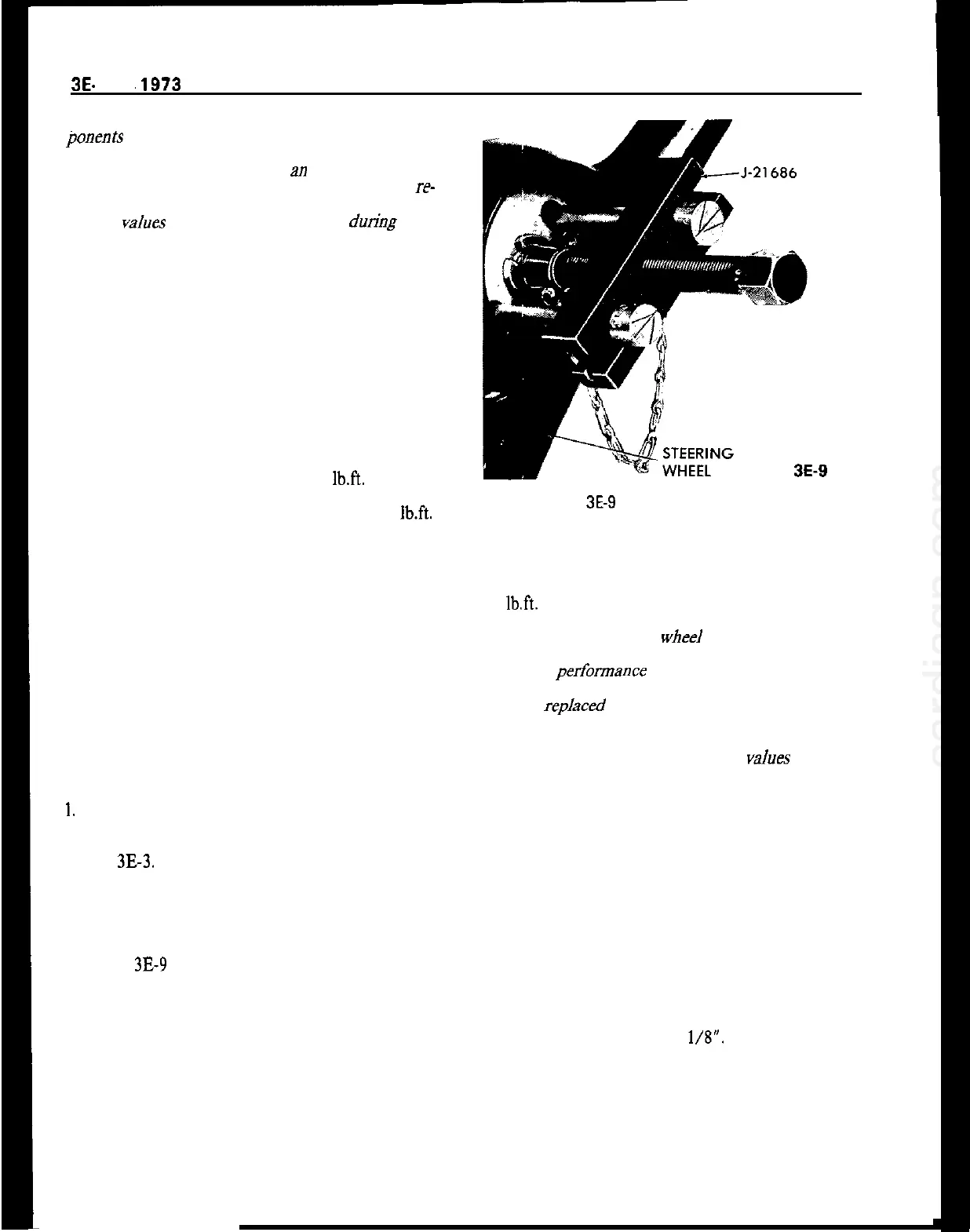
4. Install steering wheel remover J-21686 as shown
in Figure
3E-9
and pull off steering wheel.
Installation
1. Before installing steering wheel, lubricate return
pin and sliding area on directional signal switch re-
turn cams and horn contact ring.
2. Make sure that clamp bolt in steering shaft flange
is on top.
3. Make sure notch on steering shaft face is in hori-
zontal position.
Figure
3E-9
Removing Steering Wheel
4. With the steering wheel centered, place the steer-
ing wheel onto the steering shaft.
5. Install steering wheel lockplate and nut. Torque to
11
lb.ft.
CAUTION:
This steering
wheeI
to steering shaft fas-
tener is an important attaching part in that it could
affect the performance of vital components and sys-
tems, and/or could result in major repair expense. It
must be
repked
with one of the same part number
or with an equivalent part if replacement becomes
necessary. Do not use a replacement part of lesser
quality or substitute design. Torque
values
must be
used as specified during reassembly to assure proper
retention of this part.
6. Bend lockplate tabs up, connect horn cap wires
and replace cable and cap.
7. Reconnect battery.
REMOVAL AND REPLACEMENT OF HORN
CONTACT RING
1. Remove steering wheel.
2. Cut off defective contact ring at wire.
3. Strip wire approximately
l/8”.
4. Install new part and solder connection with resin
core solder.
5. Lubricate contact ring with lubriplate, or equiva-
lent.
6. Reinstall steering wheel.