GT STEERING COLUMN ASSEMBLY
3E- 47
2. Disconnect ignition (white) wire set plug.
3. Remove steering lock retaining screw. See Figure
3E-20.
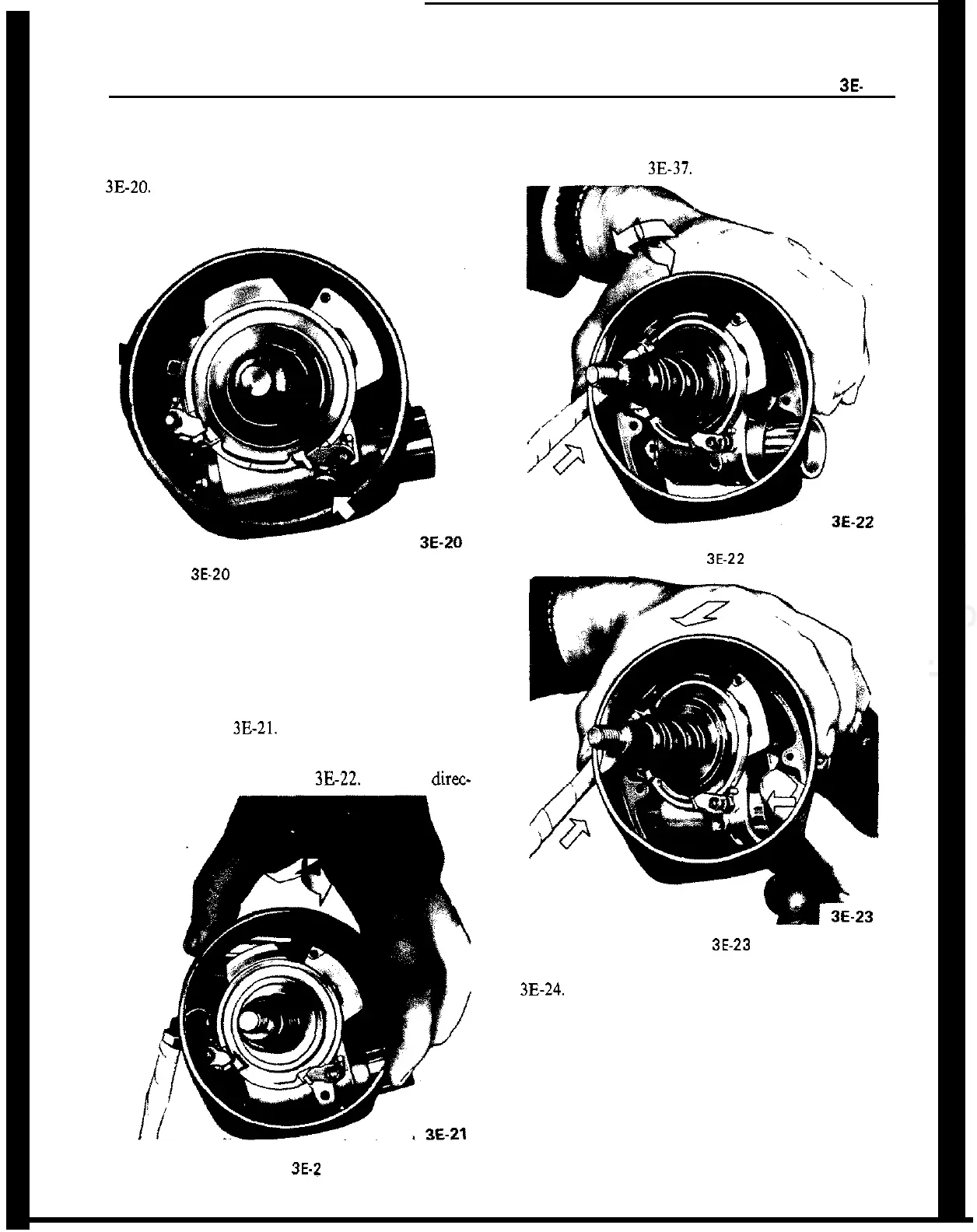
Figure 3E-20 Steering Lock Retaining Screw
4. Remove direction signal switch lever.
5. Remove three screws securing signal switch cover
to housing.
6. To remove housing cover, (a) pull cover toward
direction signal switch and move it slightly to the
right. See Figure
3E-21.
(b) Turn cover toward the
left and move it further to the right so that the left
retaining screw ear is positioned under the left signal
switch return cam. See Figure
3E-22.
(c) Insert direc-
Figure 3E-2 1
tion signal switch lever into oblong opening in cover
and push steering lock into housing and remove
cover. See Figure
3E-37.
Figure
3E-22
Figure 3E.23
7. Remove ignition switch electrical unit. See Figure
3B24.
8. Remove wires from connector plug making certain
to note location of each.
9. Tape wire ends together and remove electrical unit
and wire harness.
Installation
1. Position electrical unit wire harness through col-
umn and reconnect to connector plug.