3E- 48 1973 OPEL SERVICE MANUAL
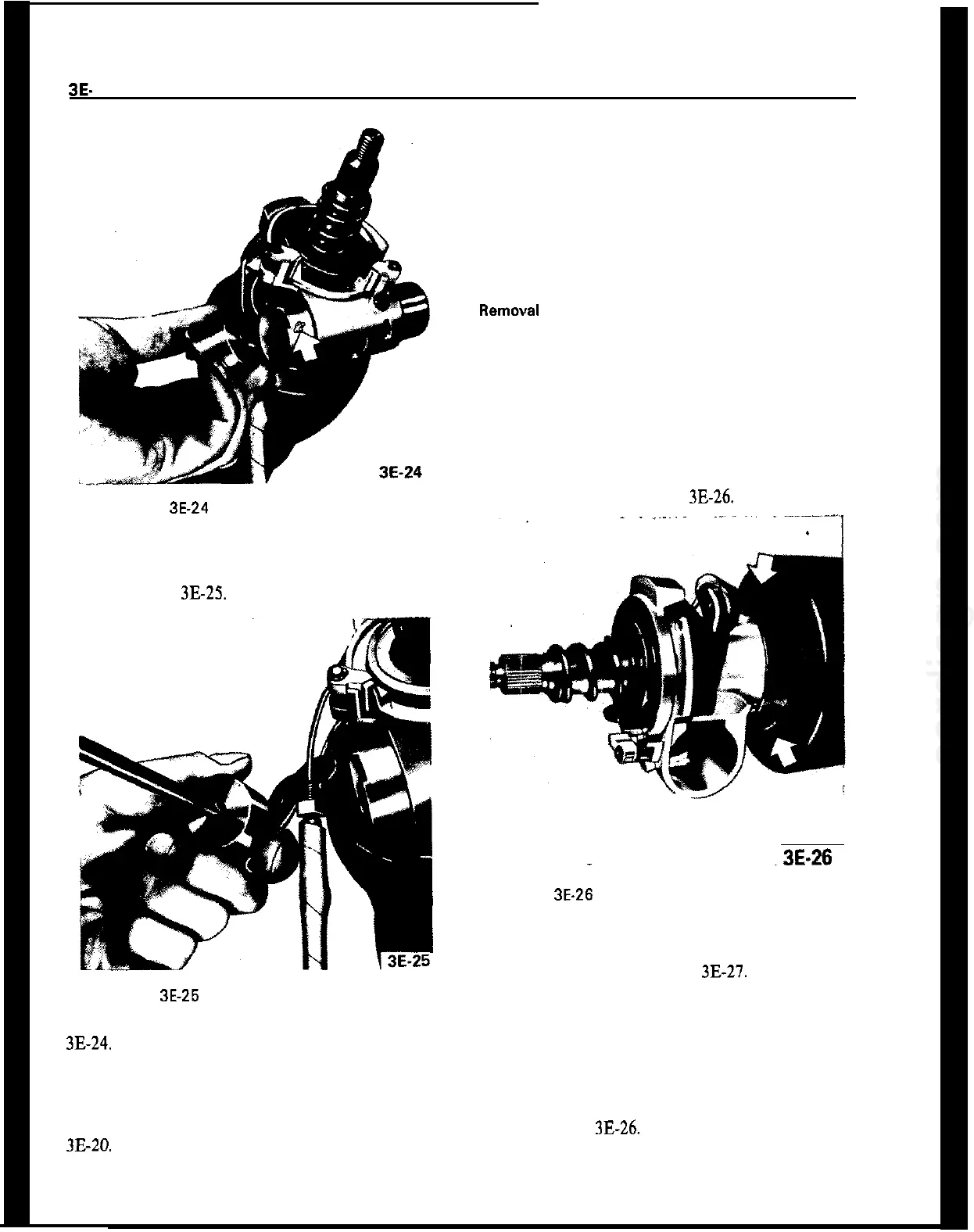
Figure 3E-24 Removing Electrical Unit
Before installing electrical unit be sore unit is in
RUN position. Using a Philips screwdriver, turn in-
ner sleeve to the tight until a springy resistance is
felt. See Figure
3E-25.
Figure 3E-25 Checking for RUN Position
2. Install ignition switch electrical unit. See Figure
3E-24.
3. Install housing cover by attaching with three (3)
screws.
4. Install steering lock retaining screw. See Figure
3E-20.
5. Reconnect ignition (white) wire set plug.
6. Install direction signal switch lever.
7. Install ignition lock cylinder. See previous para-
graph in this section.
REMOVAL AND INSTALLATION OF UPPER
STEERING BEARING AND/OR DIRECTION SIGNAL
SWITCH
1. Remove ignition switch and steering lock, see
previous paragraph in this section.
2. Disconnect direction signal (black) wire set plug.
3. Remove wires from connector plug making certain
to note location of each.
4. Remove screws and direction signal housing and
switch assembly. See Figure
3E-26.
.
.3E-26
Figure 3E-26 Removing Direction Signal Switch
Assembly
5. To remove upper bearing, pull horn wire out of
bearing housing and pry out bearing assembly using
a flat screwdriver. See Figure
3E-27.
Installation
1. If upper bearing has been removed, install by using
the thumbs of both hands being sure to line bearing
up with notched portion of housing.
2. Install direction signal housing and switch assem-
bly. See Figure 3B26.
3. Reposition wires into connector plug and connect
direction signal wire set.