RECESSES VERTICAL FOR
REMOVAL OF LEFT ROW OF
CYLINDER HEAD BOLTS
6A-16
Figure 6A-18 Recesses in Camshaft
2. Clean piston tops and combustion chambers.
Thoroughly clean all gasket surfaces on the cylinder
block and cylinder head.
3. Lightly lubricate cylinder walls with engine oil.
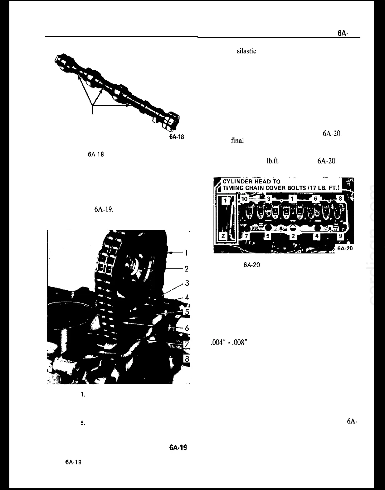
Install coolant passage rubber gasket ring in timing
case. See Figure 6A-19.
I. TIMING CHAIN
2. CAMSHAFT SPROCKET
3. SPROCKET TIMING MARK
4. TIMING CASE
5.
SUPPORT TIMING MARK
6. SUPPORT
7. CYLINDER BLOCK
6. RUBBER GASKET RING
6A-19
Figure 6A-19 Coolant Passage Rubber Gasket Ring in
Timing Case
ENGINE MECHANICAL AND MOUNTS
6A-
13
4. Apply silastic sealer or equivalent to both sides of
the cylinder head gasket where the gasket mates with
the timing chain cover, place new cylinder head gas-
ket onto cylinder block.
5. Install cylinder head. Be careful to place head
squarely over guide pins.
Rotate camshaft so that recesses are in vertical posi-
tion to allow installation of left row of bolts.
6. Install 10 head bolts. Tighten the bolts a little at
a time in the sequence shown in Figure 6A-20. Give
bolts a final torque in the same sequence. Torque to
72 lb. ft. (cylinder head cold). Use same procedure
for cylinder head to timing chain cover bolts with
final torque at 17
lb.ft.
See Figure 6A-20. These
torques apply to lightly oiled threads.
Figure 6A-20 Cylinder Head Bolt Tightening
sequence
7. Slide camshaft sprocket with assembled chain onto
camshaft and guide pin and fasten with bolts. Install
nylon adjusting screw. After sprocket has been at-
tached to camshaft, recheck alignment to see that
chain has not slipped. Close front access hole.
8. Check camshaft end clearance between cover and
nylon screw with feeler gauge. Clearance should be
.004”
-
.008”
Excess clearance can be eliminated by
carefully readjusting cover with a suitable drift.
Reconditioning Valves and Guides
1. Remove cylinder head. Place on clean surface.
Place head on bench supported at each end by a
block of wood to prevent damage to valves.
2. Using suitable spring compressor, such as J-8062,
compress valve spring and remove cap retainers. Re-
lease tool and remove spring and cap. See Figure 6A-
21.
3. Remove valves. Place valves in numerical order so
that they can be reinstalled in original location.
4. Remove all carbon from combustion chambers,
piston heads, and valves. When using scrapers or