6F. 64 1973 OPEL SERVICE MANUAL
Figure
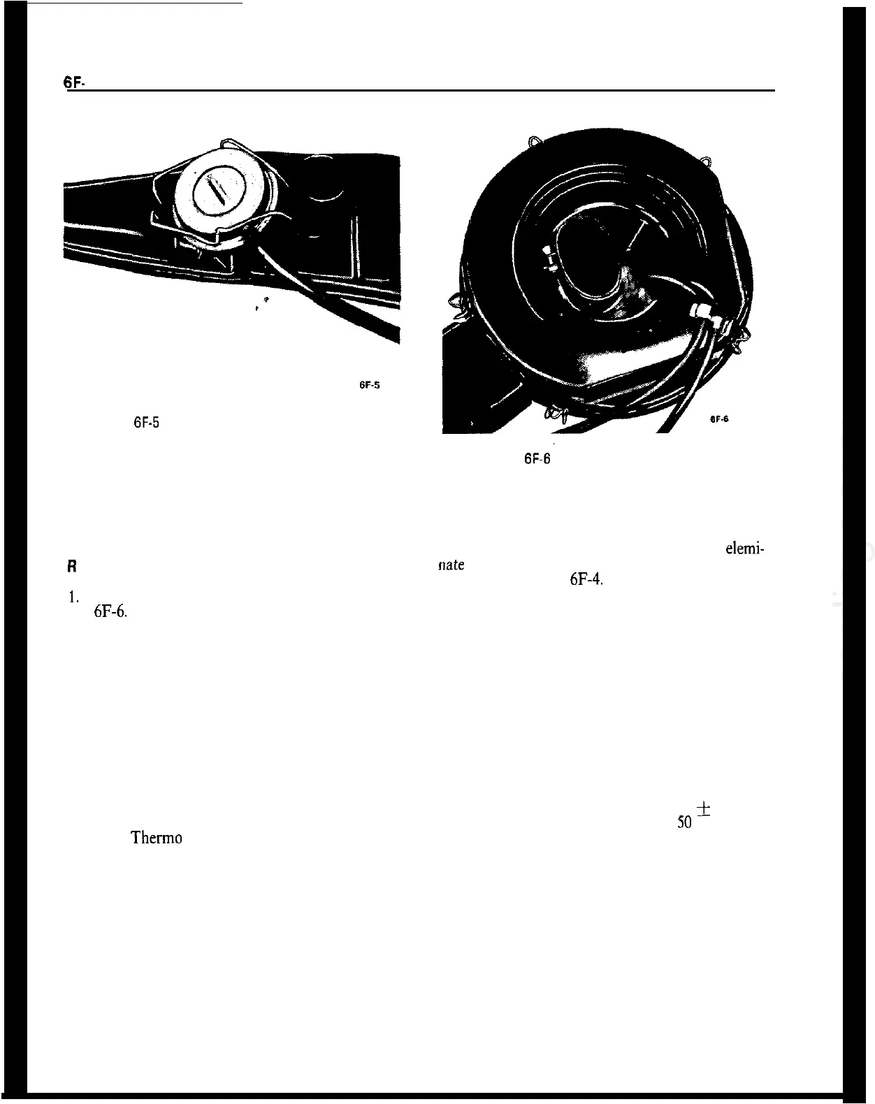
6F-5
Replacing Vacuum Motor Assembly
2. Lift vacuum motor, cocking it to one side to un-
hook motor linkage at the control door.
3. Install in reverse sequence.
R
And R Air Cleaner Sensor
1.
Remove sensor retaining clips by prying. See Fig-
ure
6F-6.
2. Pull vacuum hoses from sensor.
3. Note carefully the installed position of the sensor
SPECIFICATIONS
EMISSION CONTROL SYSTEM SPECIFICATIONS
Figure
6F-6
Replacing Sensor Assembly
so that you can install new sensor in same position.
Then remove sensor.
4. Install sensor and gasket assembly in air cleaner
in same position as noted in Step 3. This is to elemi-
“ate the possibility of interference with the air filter
element. See Figure
6F-4.
5. Install sensor retaining clip. Meanwhile support-
ing sensor around the outside rim to prevent damage
to the temperature sensing spring.
6. Reinstall vacuum hoses.
Carburetor Inlet Air Regulated Temperature
..........................................................
115”
k
20
Idle Mixture Setting (Lean From Best Idle)
.............................................................. 50
RPM
Therm0 Vacuum Switch Operating Temperature
............................................................ 220
Engine Thermostat Operating Temperature
...................................................................... 189