GA.
xl
1973
OPEL
SERVICE MANUAL
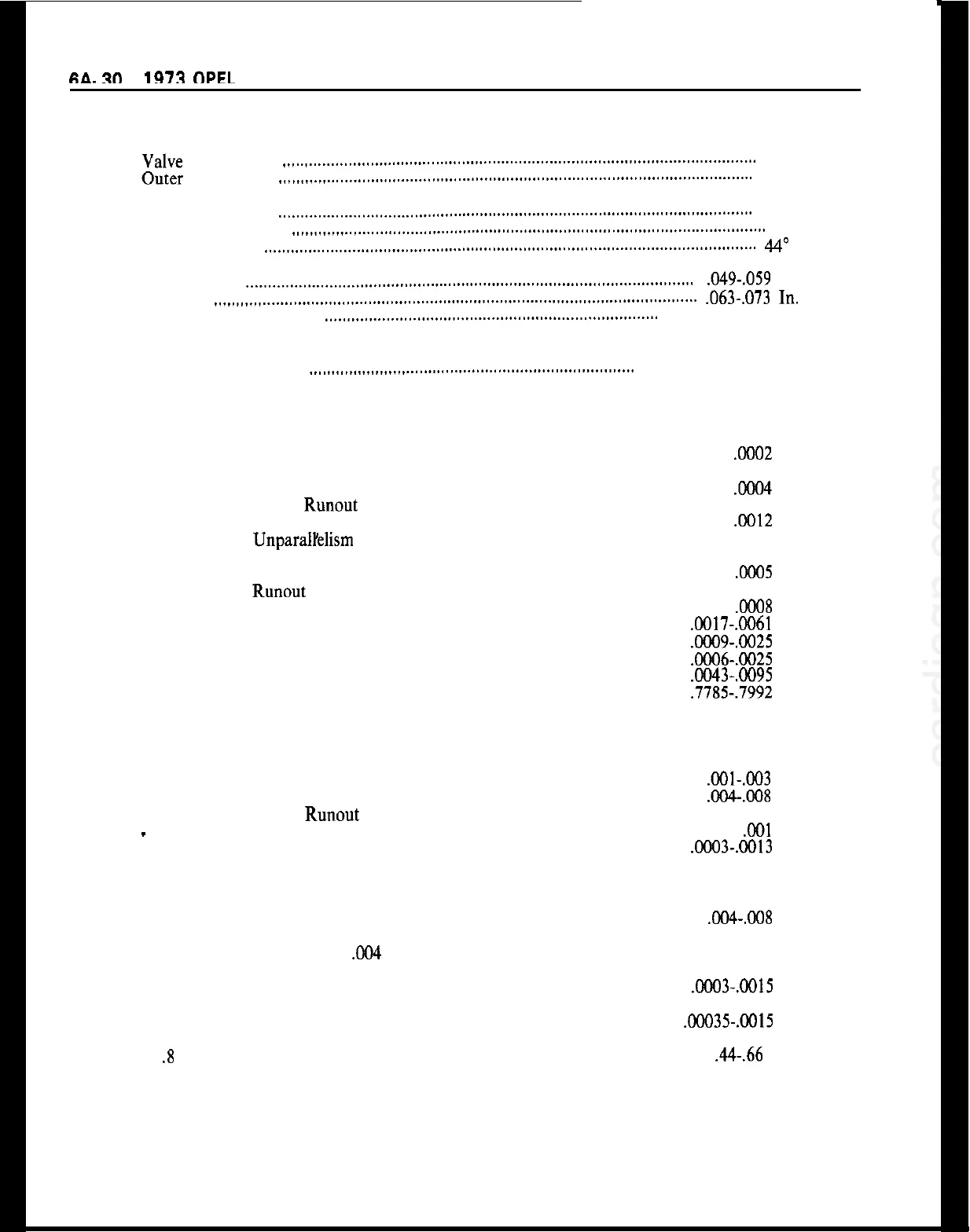
Valve Seat and Correction Angle in Cylinder Head
Intake
Valve
Seat Angle
..,._,..__....,,..,,,..,.,.,.,..............,...............................................................
45”
Outer Correction
.,,,.,,._.,._..___,,,.,,,,,.......,,.,..,...,,..,..,,..,,..,,,..............................................
30”
Exhaust
Valve Seat Angle
,,,.,,.__,.__..___.,..,,..,...,,....,..,..,..,,..,..,...,..,,,...,,.........................................
45”
Outer Correction
.,,..,,...,._.,.__....,,,.....,,,...........................................................................
30”
Valve Face Angle
,,..,,,..,.__..__.._..,,,..,,...,,......,.,..,..,..,,.,,,..,..,,,..,,,..,,,...,,................................
44”
Valve Seat Width in Cylinder Head
Intake
. . . . . . . . . . .._..._._.................,,..,.....,,..,............,...,..,,,..,,..,,...,,...,,,..,................. .049-,059
In.
Exhaust
.,..,,,..,,.___..,,..,,...,..,,,..,,...,,...,,...............,,..,,..........,,....,,...,.....................
.063-,073
In.
Valve Head Contact Area
,,..,,,..,,___.__.,,..,,..,.,,..........,...,,..,,............,,,...,.......
Aim at Centricity
Valve Clearance at 176°F. Coolant and 140°F. to 176”
Oil Temperature
Intake and Exhaust
_.,,..,,,,,,..,,....,...,,,.,.,,,.,..........................,,,..,,,,....
Zero Plus One Turn
Cranking Mechanism
Max. Permissible Out-of-Roundness of Connecting Rod Bearing
Journals
.................................................................................................................... .OC02
In.
Max. Permissible Taper of Connecting Rod and Crankshaft Bearing
Journals
.................................................................................................................... .ooO4
In.
Max. Permissible Radial Runout of Center Main Bearing
Journals When Supported in End Bearings
.......................................................... .0012 In.
Max. Permissible UnparalYelism of Connecting Rod Bearing
Journals When Crankshaft is Placed in V-Blocks so That
Main Bearing Journals Next to Each Other Are Supported
................................
0005 In.
Max. Permissible Runout of Crankshaft to Flywheel
Contact Area
..........................................................................................................
.0008
In.
Crankshaft End Play
........................................................................................
.GOl7-.CO61
In.
Main Bearing Clearance
.................................................................................... .ooO9-.@I25 In.
Connecting Rod Bearing Clearance
................................................................
.ooO6-.0025
In.
Connecting Rod End Play on Bearing Journal
..............................................
.0043-.0095 In.
Connecting Rod Bearing Length
...................................................................... .7785-.7992
In.
Crankshaft Thrust Bearing Length
.............................................................................. 1.08 In.
Valve Mechanism
Camshaft Bearing Clearance
................................................................................
.OOl-,003
In.
Camshaft End Play
..............................................................................................
.004-038 In.
Max. Permissible Radial Runout of Camshaft Center Bearing
-
Camshaft Supported in Outer Bearings
................................................................
,001
In.
Valve Lifter Clearance in Cylinder Head
Bore
.............................................. .0003-.OOl3 In.
Engine Lubricating System
Oil Pump Gear Backlash
......................................................................................
0%.008
In.
Oil Pump Gear End Play in Housing
........................................
Gears Protruding Over Edge
of Housing: Not More Than
,004
In.
Clearance of Spindle in Bore of Oil Pump Driven
Gear
.............................................................................................................. .OCO3-.0015
In.
Clearance Between Oil Pump Drive Gear and
Bushing
........................................................................................................
.00035-.OOl5
In.
Oil Pump Relief Valve Spring Pressure at a Spring Length
of
.8
In.
................................................................................................................ .44-.66
Lbs.