6A. 4 1973 OPEL SERVICE MANUAL
hand side above crankshaft sprocket, has a plunger
head with oil- proof and wear-resistant synthetic
rubber pad, which is pressed against chain by both
spring and oil pressure.
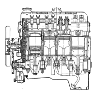
Figure
6A-2
Sectional View. Timing System
The top end of the short, light-weight hydrauric
valve
liffers
is provided with a cup in which tits the
ball end of a stud engaged in an elongated hole in
rocker arm, thus maintaining transverse alignment
of the rocker arm.
The rocker
xrn
is a steel stamping and pivots on
a ball secured by a self-locking nut on a stud screwed
into the cylinder head. This arrangement permits
easy valve clearance adjustment. All valves have oil
seals installed between valve spring and cap.
The
fuelpump
is located at bottom left-hand side
of timing case and operated by, a cam integral with
distributor drive gear riveted
‘to
distributor drive
shaft.
The aluminum alloy cast intake manifold with
smooth walls provide better charge of cylinders,
especially at high engine RPM. It is a four-port
manifold, i.e. there are separating walls between all
arms, one for each cylinder. An adapter for crank-
case ventilation hose leading to rocker arm cover is
arranged on front portion of intake manifold.
Hot exhaust gases are used for heating a vaporization
plate located at bend of intake manifold below carbu-
retor and communicating with its tinned underside
with the interior of the exhaust manifold to ensure
that only vaporized fuel reaches the cylinders.
LUBRICATION SYSTEM AND OIL PUMP
The engine is lubricated by a forced feed system
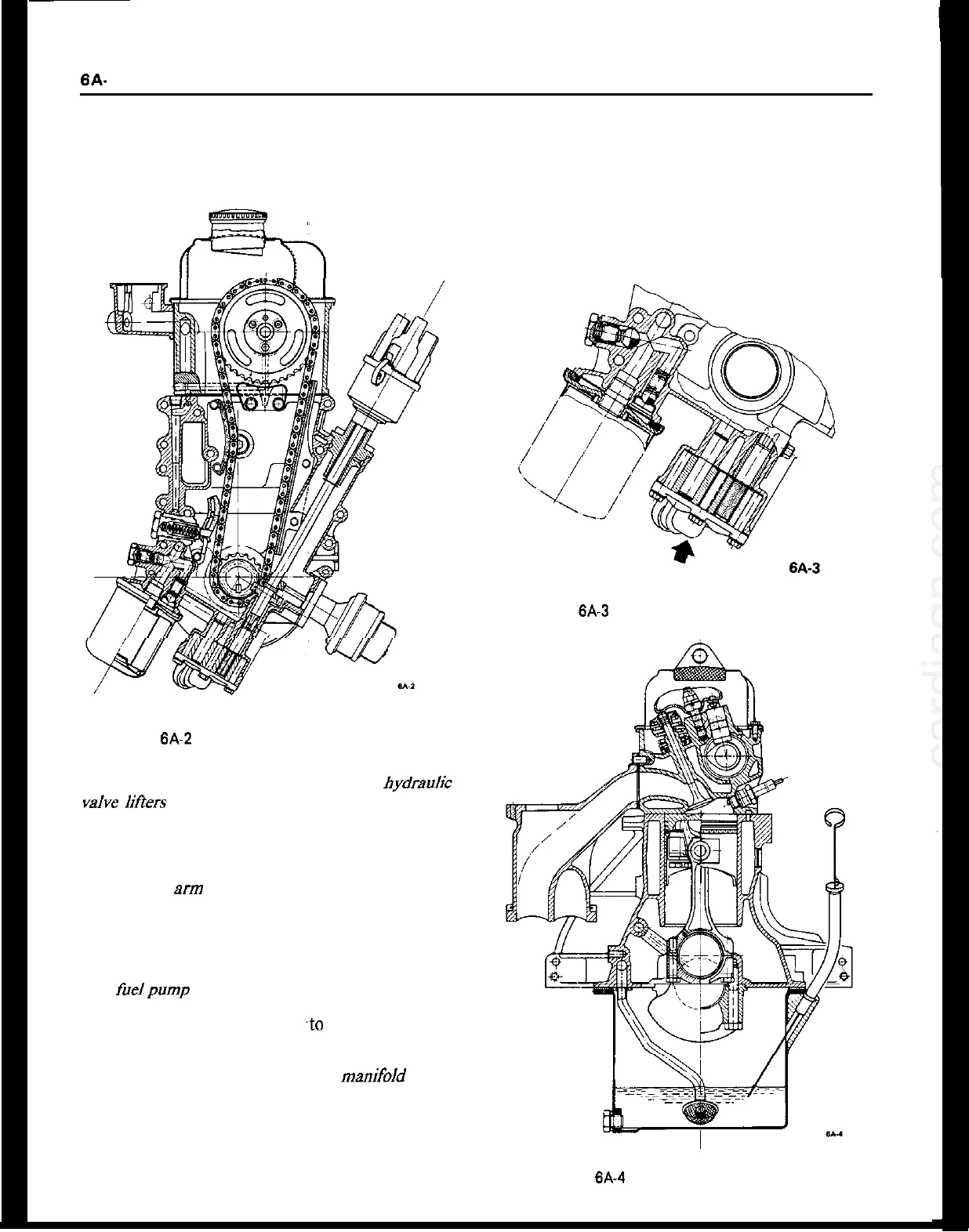
Figure
6A-3
Oil Pump Pressure Relief Valve
Figure 6A.4 Rear Cross Sectional View