CARBURETOR AND THROTTLE LINKAGE 6E- 51
water, adjust the throttle stop screw to read 6 inches
of water (3 inches down and 3 inches up).
4. Disconnect manometer and reconnect the vacuum
advance hose.
5. Adjust idle air speed screw and mixture screw to
obtain maximum idle at 850 to 900 R.P.M. (auto-
matic transmission) or
900
to 950 R.P.M. (manual
transmission).
6. Make final adjustment by turning idle mixture
screw in to reduce idle speed 50 R.P.M.
7. Install red plastic caps over the air speed screw
and idle mixture screw. Replace plastic cap over the
throttle valve stop screw and secure in place with
Loctite.
Fast Idle Speed Adjustment
1.
Remove air cleaner cover.
2. With engine off, open the throttle halfway and
close the choke valve, release the throttle, then re-
lease the choke.
3. Start engine without moving the throttle. Adjust
to 3200 to 3300 R.P.M. using 2 nuts on fast idle rod.
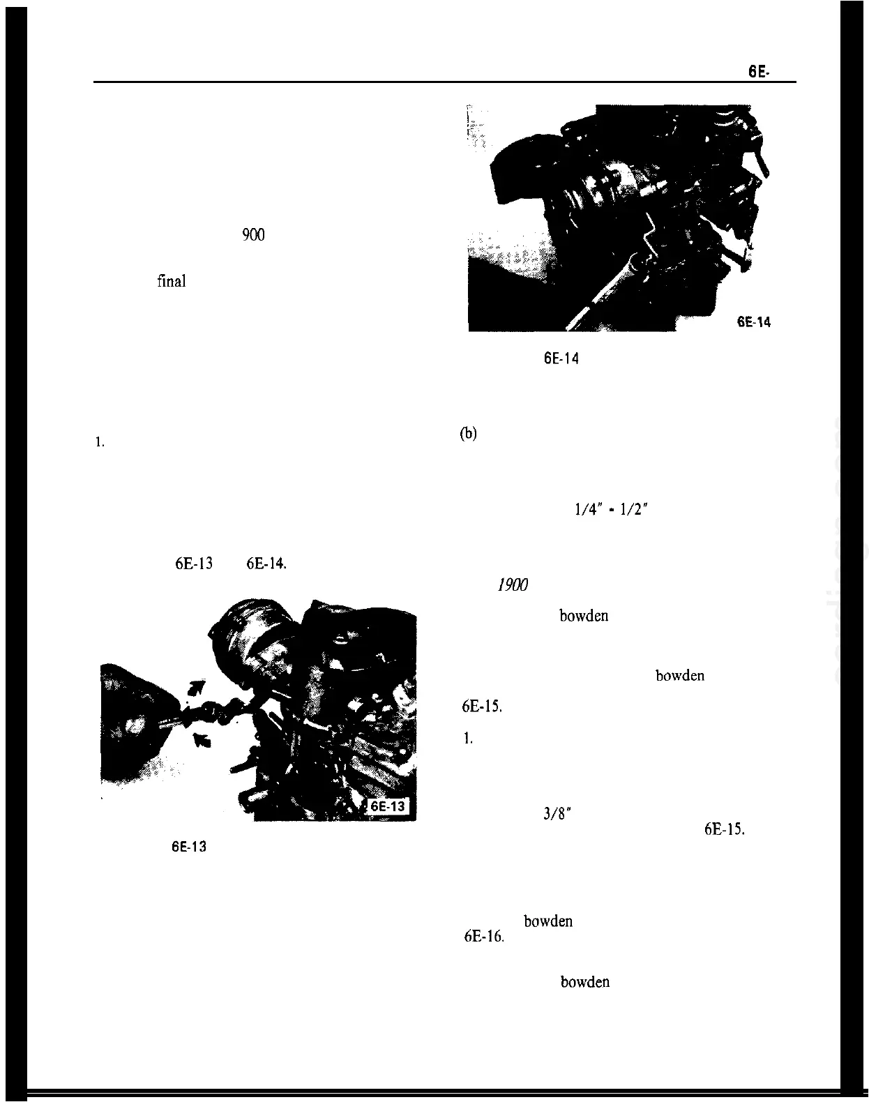
See Figures 6E-13 and
6E-14.
Figure
6E-13
Decreasing Fast Idle Speed
CARBURETOR LINKAGE ADJUSTMENT
GT Series
1. Remove air cleaner.
2. Have helper depress accelerator pedal to floor and
check to see if wide open throttle is reached at carbu-
retor.
3. If adjustment is necessary, proceed as follows:
6E-14
Figure
6E-14
Increasing Fast Idle Speed
(a) Unhook accelerator pedal return spring.
(b)
Remove lock spring at upper end of vertical con-
trol rod and detach rod.
(c) Lengthen or shorten control rod so that wide
open throttle is obtained at the carburetor when ac-
celerator pedal is
l/4”
-
l/2”
from floor mat.
(d) Reinstall rod, lock spring and pedal return
spring.
Opel
19W
and Manta Series
The carburetor bowden control wire is properly ad-
justed if, with correctly-adjusted engine idle speed,
engine at operating temperature and accelerator
pedal at an angle of 25 degrees to the vertical plane,
the ball (A) of the carburetor bowden control wire
rests against the accelerator pedal lever. See Figure
6E-15.
1.
Position accelerator pedal at an angle of 25 degrees
to the vertical plane. To do this, loosen lock nut of
adjusting bolt (c) and unscrew adjusting bolt a few
turns.
Squeeze a 1 3/S” wood block (D) between accelera-
tor pedal and dash panel. See Figure
6E-15.
Screw in adjusting bolt until the accelerator pedal
lever releases the wood block (D). Tighten lock nut.
2. Adjust bowden control wire at adjuster. See Figure
6E-16.
Prior to doing this, adjust engine idle speed
with engine at operating temperature.
Set carburetor bowden control wire adjuster at the
bracket so that the ball (A) of the control wire rests
against part (B) of the accelerator pedal lever and the
wire core between bracket and segmental disc is not
sagging.


 To Next Page