KRM-X® Duct Smoke Detector
8 | 10 | Fire Protection | Data sheet No. 41350 | Version 01-2019
6. Installation outdoors or in a cold environment
• A special WDG-type splash-proof housing is available for protection of
smoke detectors exposed to the open air or a cold environment. This
housing prevents the warm air in the smoke detector duct from con
-
densing. The interior of the housing is insulated with foam rubber.
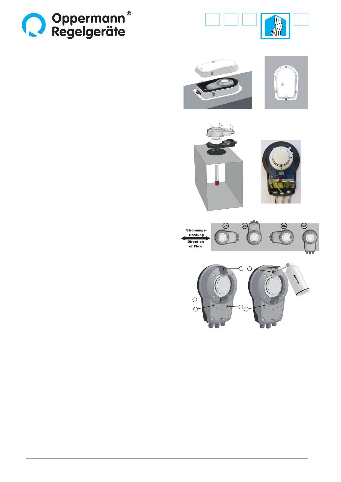
7. Installing the housing with the sensor
• Attach the housing base with the electronics and sensor to the adapter
plate. The housing can be attached in any of the four orthogonal orien-
tations. The direction of the housing has no eect on the measurement
r
esult. You can optimally align the housing with the sensor.
• Wire the device according to the applicable circuit diagram.
• Caution: Wiring and electrical connections may only be done by a duly
qualied electrician.
• Make sure that all cables are connected in accordance with the applica-
ble electrical regulations. The cable jacket must reach as close as possi-
ble to the terminal block. Wires longer than 10 mm must be xed near
the t
erminal block using a cable clip or the like or must be insulated in
pairs with a suitable protective tube (see application example).
• Check that the gaskets in the housing top are correctly positioned.
• Complete the installation by snapping on and tightening the housing
top (ensuring that the catch at the lower end of the housing snaps in
correctly; observe the specied mounting torque of 1.2 Nm).
8. Testing the duct smoke detector
• After completing the installation work, properly wiring the device
(please note the separate data sheets / circuit diagrams) and applying
power, the duct smoke detector is operational.
• The green LED (12) lights up.
• Press the alarm / reset button (9) to perform a simple initial functional
test. All LEDs must light up and all relays drop out. The units con-
nected to the relays are activated! The display (11) indicates the
cur
rent degree of sensor contamination. On releasing the button, all
LEDs go out except for LED (12), which shows the supply voltage, and
the relays pull in. A test opening (14) is available for testing the duct
smoke detector. Open the test hole plug. Then spray test spray into the
test opening until the smoke detector triggers. Take care not to apply
too much test spray, since this would contaminate the smoke detector,
possibly causing it to indicate a higher contamination level after the
next start or reset.
• Caution: Take care to close the test hole opening after the test to
prevent the smoke detector from drawing in false air. False air could
prevent the smoke detector from triggering when it should. The alarm/
reset button lights up, and the relays drop out. The electronic system
goes into alarm state and locks up. Press the alarm/reset button to
release it. The sensor must be free of smoke and test gas during
reset. If there is still test gas in the chamber, the device will indicate a
higher contamination level. In this case, wait a while and then perform
a reset by disconnecting the voltage or perform an external reset. If
necessary, remove the housing cover and blow out the smoke detector.
9. Final review
• Are all screws tight?
• Is the adapter plate properly mounted in terms of ow
direction?
• Are all gaskets in the correct position?
• The blue LED must not light up when airow > 1 m / s
during operation.
Use the test opening for performing the functional test.
Caution: The test opening should always be closed
during operation, as this would otherwise prevent
smoke detection!
11
9 9
14 14
12
wiring example:
1)
The WDG-X special housing is not covered by the VdS
approval.
 Loading...