KRM-X® Duct Smoke Detector
2 | 10 | Fire Protection | Data sheet No. 41350 | Version 01-2019
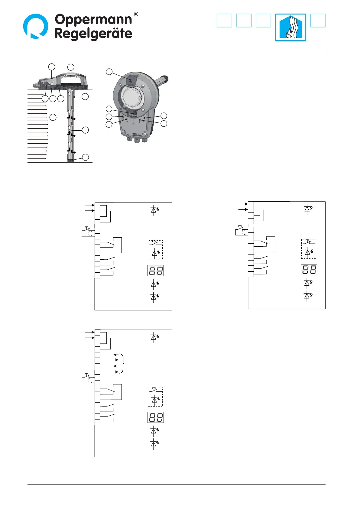
power supply
230 V AC
test/reset
(NC contact)
9
10
11
12
13
14
15
green
16
17
yellow
blue
smoke alarm
smoke alarm
service signal
contamination
red
test/reset
3
4
power supply
230 V AC
1
2
KRM-1
1
2
3
4
5
6
7
8
15
Electrical connection
10
9
11
12
13
14
1 Adapter plate with gasket
2 Patented measuring tube
3 End cap
4 Rubber bushing
(only for insulated or circular ducts)
5 Housing base with gasket
6 Electronics
7 Optical smoke detector
8 Housing top with gasket
9 LED red: alarm/reset button
10 LED yellow: failure
11 LED display: sensor contamination in %
12 LED green: in operation
13 LWD blue: airow below 1 m/s
14 Opening for test gas
15 Air duct
All contact diagrams are shown
in the power-o state
(alarm) / contamination > 70%
optional informative
RS 485 bus interface
(see KRM-X-2-MOD/-BAC)
Remote reset/test (terminal 9 +10): if bridge circuit is removed,
a oating NC contact must be connected.
Note: The oating switching contacts (terminals 11 – 17) should be
assigned as uniformly as possible to an installation category
according to EN 60730-1. These switching contacts are to be used for
230 V A
C only for or 24 V AC / DC only. Combinations are not permit-
ted unless at least one contact between dierent potentials remains
unassigned
. Mixed congurations of safety extra-low voltage
(SELV) and low voltage are not allowed. The assembly may only be
operated on one mains phase. Disconnection / Electrical protection
equipment must be provided by the customer.
KRM-X.-1-xx (230 V versions) with a fuse of 16 A;
KRM-X-2-xx (24 V versions) with 4 A.
KRM-X-2, 24 VKRM-X-1, 230 V
KRM-X-2-MOD, 24 V
KRM-X-2-BAC, 24 V
power supply
24 V AC/DC
test/reset
(NC contact)
9
10
11
12
13
14
15
green
16
17
yellow
blue
smoke alarm
smoke alarm
service signal
contamination
red
test/reset
3
4
power supply
24 V AC/DC
1
2
KRM-2
power supply
24 V AC/DC
test/reset
(NC contact)
9
10
11
12
13
14
15
green
16
17
yellow
blue
smoke alarm
bus B
bus B
bus A
bus A
smoke alarm
service signal
contamination
red
test/reset
3
4
5
6
7
8
power supply
RS485
(informative)
power supply
24 V AC/DC
1
2
KRM-2-MOD
 Loading...