- 7 -
3.1 The Control Components
All directions (RH, LH) are given as seen from the control panel in driver`s cabin.
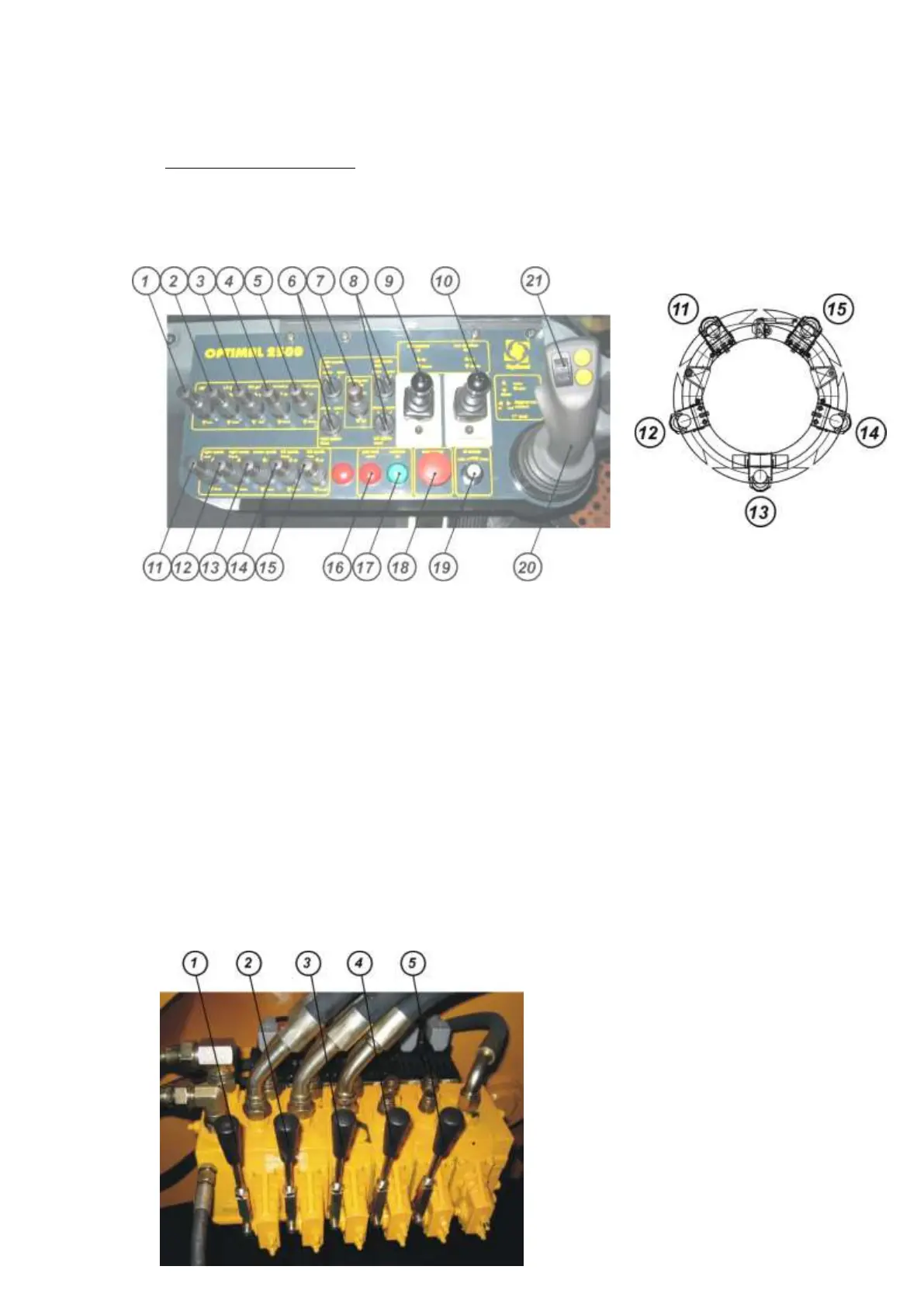
3.1.1 Control Panel Inside the Driver’s Cabin Location of Spades
1) gate lock – unlock / lock 11) left spade, rear – up / down
2) LH gate – open / close 12) left spade, front – up / down
3) RH gate – open / close 13) center spade – up / down
4) root ball pad LH – up / down 14) right spade, front – up / down
5) root ball pad RH – up / down 15) right spade, rear – up / down
6) preselect folding out spades - LH rear / front 16) indicator light – gate lock open
7) folding out spades – in / out 17) indicator light – controls on
8) preselect folding out spades - RH rear / front 18) emergency off
9) rear stabilizer LH – up / down 19) oil supply min/max
10) rear stabilizer RH – up / down 20) ▲ main lift arm – up
▼ main lift arm – down
◄► digging head rotation – in / out
21) ▓ articulated lift arm – up / down
3.1.2 Valve Bank on the Base Frame
1) main lift arm – up / down
2) digging head rotation – in / out
3) articulated lift arm – up /down
4) rear stabilizer LH – up / down
5) rear stabilizer RH – up / down