Do you have a question about the Optoma BM-5001U and is the answer not in the manual?
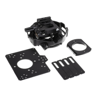
Attach connection block (AA) to plate (A) using screws (D) and spacers (L).
Attach plate (A) to projector using screws (O), washers (K), and spacers (L).
Attach connection block (AA) to plate (A) using screws (D) and spacers (L).
Attach plate (A) to projector using screws (O), washers (K), and spacers (L).
Attach connection block (AA) to plate (A) using screws (D) and spacers (L).
Attach plate (A) to projector using screws (O), washers (K), and spacers (L).
Attach connection block (AA) to plate (A) using screws (D) and spacers (L).
Attach plate (A) to projector using screws (P) and spacer (M).
Attach connection block (AA) to plate (A) using screws (D) and spacers (L).
Attach extension brackets (B) to plate (A) using screws (Q) and to projector using spacers (L), washers (K), and screws (O).
Attach connection block (AA) to plate (A) using screws (D) and spacers (L).
Attach extension brackets (B) to plate (A) using screws (Q) and to projector using spacer (M), screw (O), washers (K), and spacers (L).
Attach connection block (AA) to plate (A) using screws (D) and spacers (L).
Attach extension brackets (B) to plate (A) using screws (Q) and to projector using spacers (L), washers (K), and screws (O).
Attach connection block (AA) to plate (A) using screws (D) and spacers (L).
Attach extension brackets (B) to plate (A) using screws (Q) and to projector using spacers (L), washers (K), and screws (O).
Attach connection block (AA) to plate (A) using screws (D) and spacers (L).
Attach extension brackets (B) to plate (A) using screws (Q) and to projector using spacers (L) and screws (R).
Attach connection block (AA) to plate (A) using screws (D) and spacers (L).
Attach plate (A) using screw (Q) and attach to projector using spacers (L), washer (K), washer (N), and screws (O). Attach bracket (B) using screw (O), washers (K), and spacers (L).
Attach connection block (AA) to plate (A) using screws (D) and spacers (L).
Attach extension brackets (B) to plate (A) using screws (Q) and to projector using spacer (M), screw (P), washers (K), and spacers (L).
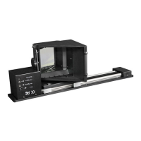
Slide connection block (AA) with projector mount (C) and tighten captive screw.
Insert screw (E) through projector mount (C) into connection block (AA) and tighten with wrench (F).
| Material | Aluminum |
|---|---|
| Mount Type | Ceiling |
| Adjustability | Tilt |
| Weight Capacity | 15 kg |
| Product Type | Projector ceiling mount |