10
71SO-TOOLCT PROCEDURE BELOW,
FOR 71SO-TOOL, SEE PAGE 8
FOR 71SO-TOOLC, SEE PAGE 9
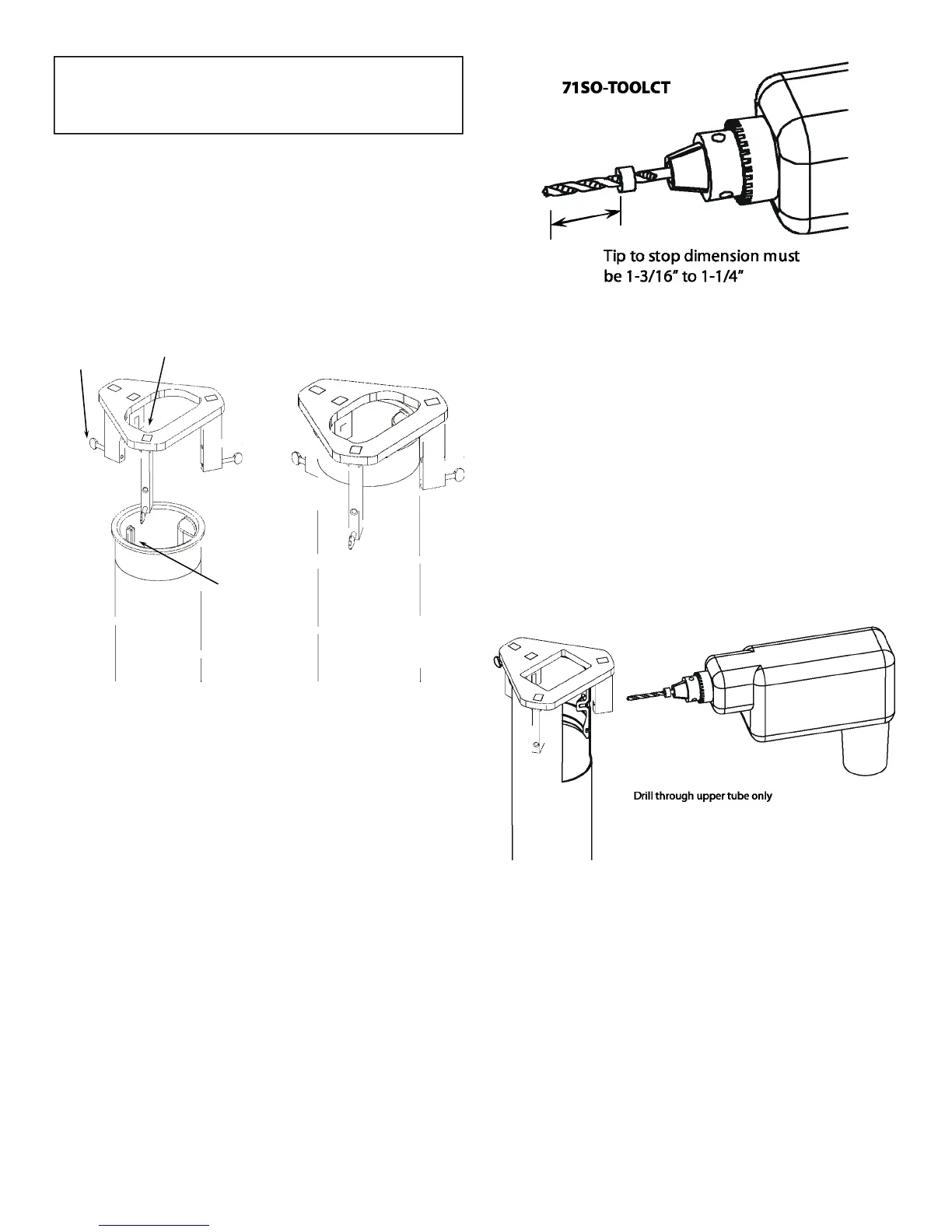
STEP 9C: INSERT 71SO-TOOLCT OVER INLET TUBE
To install the 71SO-TOOLCT (sold separately) over the
inlet tube, rst loosen the thumb screws, so the tool can
pass freely over the inlet tube ange. Align the slot on
the tool with the key on the inlet tube and insert the
tool down. See Figure 9C .
STEP 10C: TIGHTEN THE 71SO-TOOLCT
Ensure that the tool seats at against the top of the inlet
tube. To prevent vertical movement of the tool during
drilling, hand tighten the thumb screws against the up-
per drop tube. See Figure 10C.
STEP 11C: PREPARE DRILL AND BIT
Conrm that the stop on the 3/16” drill bit supplied
with the 71SO-TOOLCT is in the correct position before
drilling. The stop is factory installed at a distance be-
tween 1-3/16” to 1-1/4” from the tip with the 71SO-
TOOLCT. If the stop is not at the correct position it must
be xed before drilling.
CAUTION: If the drill stop is not in the proper loca-
tion failure of a pressure decay leak test may result.
STEP 12C: DRILL HOLES
With the inlet tube and 71SO-TOOLCT in place, carefully
drill a 3/16” diameter hole in the upper tube using the
hole in the 71SO-TOOLCT as a guide. The drill stop is
positioned so it will bottom out against the tool after
the bit has drilled through the upper drop tube. If the
stop is positioned wrong either no hole will be drilled,
or a through hole could potentially be drilled through
the inlet tube. If no hole is drilled return to step 11C
and check the stop dimension. If a hole is drilled
through the inlet tube or into the screw hole the assem-
bly is not salvageable. Drill (2) more holes in the two
remaining guide holes.
Tool Slot
Loosen
thumb
screws
Inlet
Tube
Key
Hand tighten
thumb screws
Figure 9C
Figure 10C
Figure 11C
Figure 12C
 Loading...