11
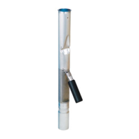
STEP 13: DIMPLE FIRST HOLE
Remove tool. Remove any chips or burrs from the drill-
ing operation. Place the assembly on a solid surface.
Using the punch supplied with the 71SO-TOOL, 71SO-
TOOLC, and 71SO-TOOLCT, align the tip of the punch
with the drilled hole and dimple the upper drop tube by
striking the punch with a hammer until the drop tube is
formed into countersunk hole in the inlet tube. After
punching, remove any chips that may have fallen into
the inlet tube screw hole.
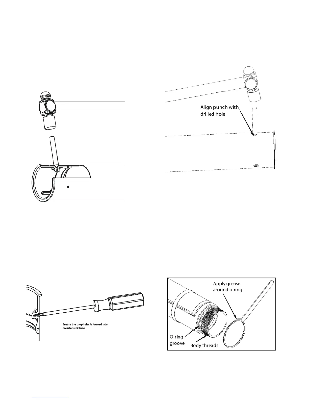
STEP 14: ASSEMBLE FIRST SCREW
Ensure that the drop tube was formed into the counter-
sunk screw hole as shown in Figure 14 if not return to
Step 13. Apply black moly grease to screw and tighten
rst screw into inlet tube with a screwdriver. Use only
the taptite screws that are supplied with the unit. Seat-
ing torque is 20 in-lbs min. to 35 in-lbs max. Screw head
should be ush with the drop tube. Do not over tight-
en.
STEP 15: DIMPLE REMAINING HOLES
Remove any chips or burrs from the drilling operation.
Dimple the next (2) holes as done in Step 13. Make sure
the assembly is on a solid surface when punching. After
punching, remove any chips that may have fallen into
the inlet tube screw hole.
STEP 16: ASSEMBLE OTHER SCREWS
Apply black moly grease to screws and tighten the oth-
er (2) screws into inlet tube with a screwdriver as done
in Step 14. Use only the taptite screws that are supplied
with the unit. Seating torque is 20 in-lbs min. to 35 in-
lbs max. Do not over tighten.
STEP 17: APPLY GREASE TO LOWER O-RING AND
BODY THREADS
Apply black moly grease to the lower tube o-ring and
body threads as shown. Make sure coverage is com-
pletely around the o-ring. Install o-ring in groove just
above threads.
Figure 13
Figure 14
Figure 15
Figure 17
 Loading...