12
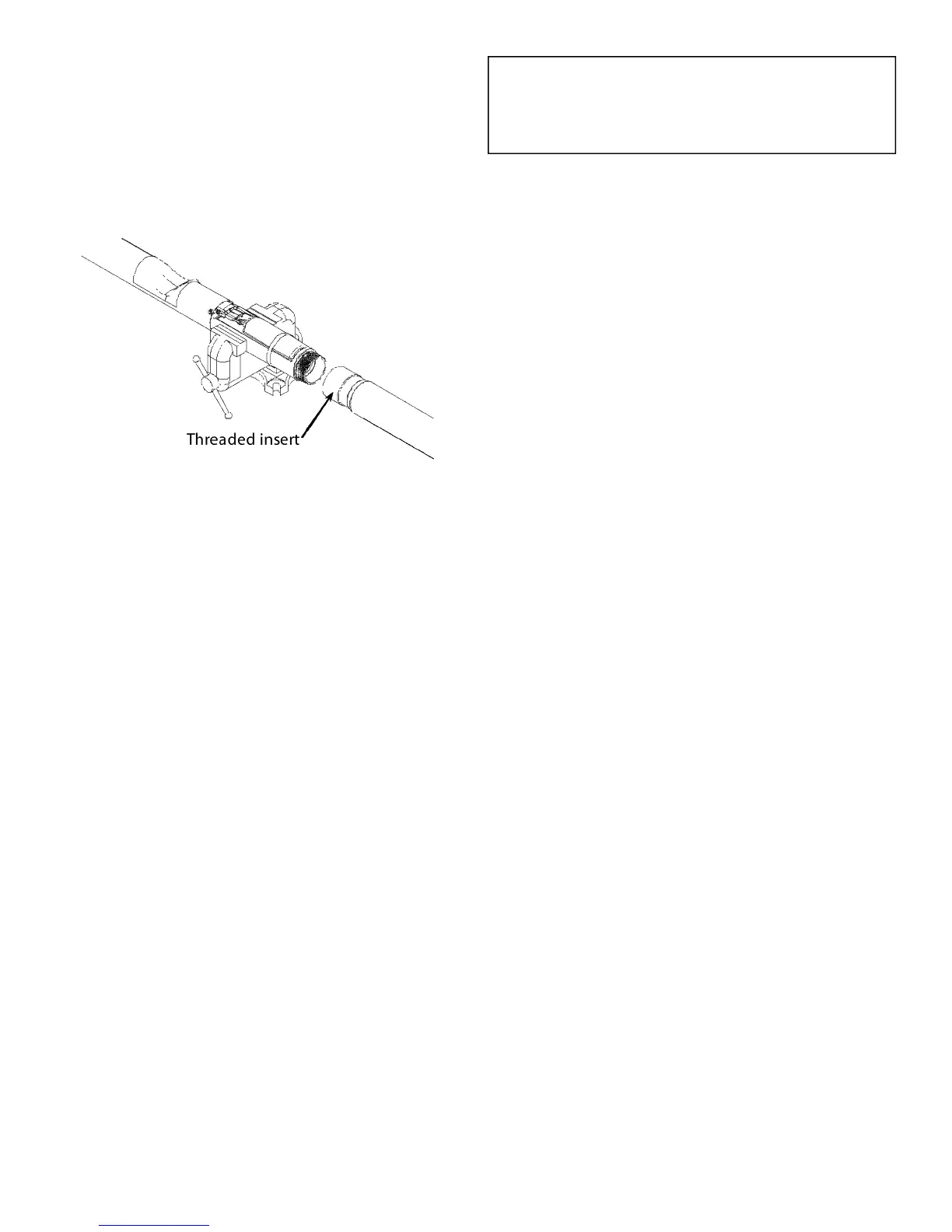
STEP 18: LOWER TUBE ASSEMBLY
If a vise is used, clamp on the valve body casting only to
avoid damage to the oat and tubes. Thread the lower
tube onto the valve body until the lower tube bottoms
out on valve body. Tube can be tightened by hand or
with a strap wrench. If a strap wrench is used try to po-
sition it on the threaded insert portion of the lower tube
to prevent damaging the tube.
NOTE: Before installing the valve in the tank, a pres-
sure test can be performed on the valve to check for
vapor tightness. Seal o both ends of the tube with
inatable plumber’s plugs. Apply a maximum 10"
W.C. (1/3 PSI) air pressure. If pressure does not hold
and a leak can be located with soap solution, do not
install the valve. Send the valve back to OPW for
warranty evaluation.
CAUTION: Do not over-pressurize. Excess pressure
can damage the valve.
STEP 19: CUT LOWER TUBE
Measuring from the underside of the inlet tube ange,
mark the overall length of the drop tube a distance of
(B) minus 6". Determine dimension (B) from the meas-
urements taken in Step 1, Figure 1 (Top of the Face Seal
Adapter below the drain valve outlet in the spill con-
tainer to the bottom of the tank). Saw o the excess
tube at a 45-degree angle or per local codes or require-
ments and le o any sharp burrs (Refer to Figure 24).
Optional: Install the OPW Tank Bottom Protector on
the lower tube (Refer to Installation instructions sup-
plied with the Tank Bottom Protector).
IMPORTANT: Remove all chips and shavings out of the
cut end of the tube. DO NOT remove chips and shav-
ings by dumping thru valve body.
FOR STANDARD VAPOR TIGHT MODELS, PROCEED
TO STEP 20 ON PAGE 14.
FOR TESTABLE MODELS, PROCEED TO PAGE 13.
Figure 18
 Loading...