13
TESTABLE PROCEDURE ONLY, FOR STANDARD MOD-
ELS, PROCEED TO NEXT PAGE.
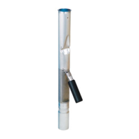
STEP 1T: INSTALL SOCKET ADAPTOR ASSY
Put cable thru threads in inlet tube and out thru cable
port on side of inlet tube. Thread the socket adaptor
assembly nger tight into the inlet tube. Note: the ca-
ble port on the inlet tube must be in line with the oat
as shown previously in Figure 8A.
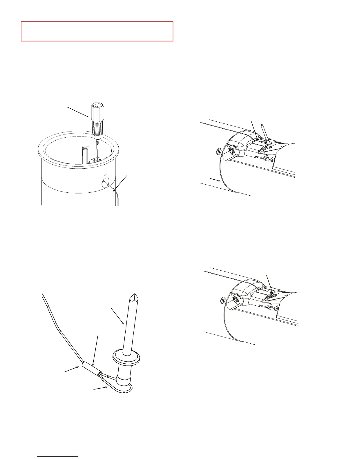
STEP 2T: PASS CABLE THRU FERRULE
Pass cable thru ferrule. Loop cable and then pass cable
back thru ferrule. Keep ferrule loose until cable length
is determined in the next step. Note: if cable end frays
it may be necessary to trim the cable again to pass thru
ferrule.
STEP 3T: DETERMINE CABLE LENGTH
Run cable along upper tube and over the top plate on
the oat bracket as shown. With the oat in the down
position (as shown in Figure 3T) align loop in cable with
rivet and top hole in oat bracket. Use the rivet as a
template to size the loop in the cable and pull cable
tight and crimp ferrule with crimping tool / pliers onto
cable at this location. Trim excess cable with wire cut-
ter / scissors. For reference, from the seam where the
upper tube and valve body meet to the end of the cable
after trimming will require approximately 3.5” of cable.
STEP 4T: ATTACH CABLE TO FLOAT BRACKET
Ensure cable is over the oat bracket. Using the sup-
plied rivet align loop in cable with top hole in oat
bracket and pass rivet thru cable loop and oat bracket
hole. Using rivet tool for 1/8” dia mandrel attach rivet
and cable to the oat bracket. See last page for list of
replacement cable parts.
STEP 5T: ENSURE PROPER CABLE OPERATION
Unthread the socket adaptor assembly from the inlet
tube and ensure oat and poppet move freely when
socket adaptor assembly is pulled on. It should only
require 3” to 4” of movement in order to actuate the
oat and poppet. Thread socket adaptor assembly n-
ger tight into inlet tube after testing.
Socket
adaptor
assembly
Cable
port
Ferrule
Trim
cable
after
step 3T
Loop
1/8” mandrel
rivet
Figure 1T
Figure 2T
Cable over oat bracket
Seam
Attach rivet to top hole
Figure 3T
Figure 4T
 Loading...