14
STEP 20: PREPARE FILL RISER FOR VALVE INSERTION
IMPORTANT: Inspect the riser pipe for any foreign ma-
terial. Over spray from tank relining or any internal
burrs inside of pipe must be removed prior to installa-
tion. Failure to have an unobstructed riser pipe may
prevent proper installation or operation of the valve.
Thoroughly clean top of riser pipe.
STEP 21: REMOVE ELASTIC BAND
Remove the elastic band securing the oat to the valve
body. The oat will move into an outward position.
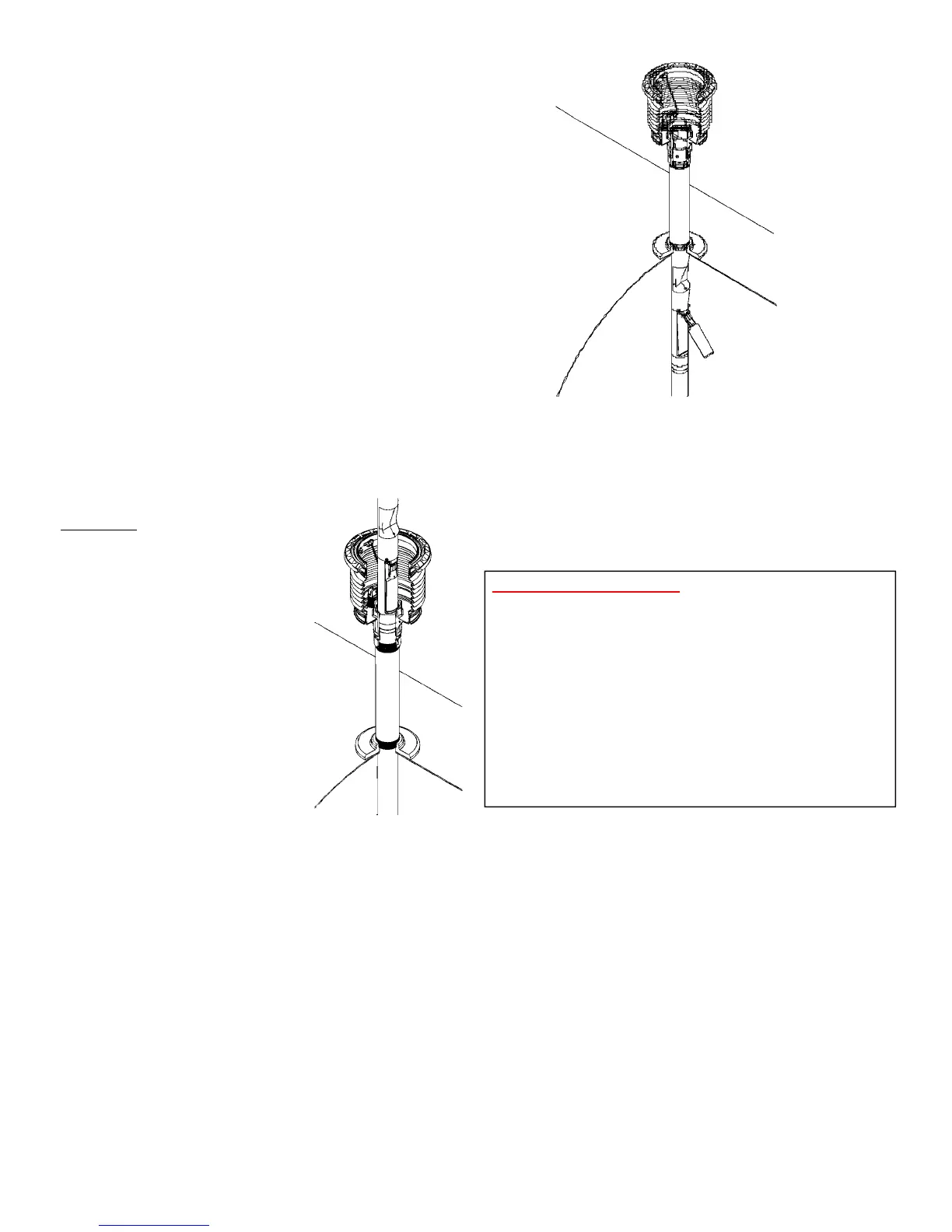
STEP 22: INSERT DROP TUBE
Make sure the upper O-Ring gasket is under the ange
of the inlet tube. Hold the oat down against the valve
body and slowly insert the drop tube overll valve into
the riser pipe. Do not force valve into the riser pipe. If
any obstruction or foreign matter interferes with
smooth insertion of the valve, the riser pipe must be
cleared.
WARNING
Failure to follow the assembly
and installation instructions or
use of excessive force to insert
the OPW 71SO will VOID THE
WARRANTY.
Diculty in removing the existing
ll tube (if there is one) means
there may be an obstruction in the
riser pipe. Look for burrs, defor-
mations, excess tank lining materi-
al or other projections that may
interfere with easy insertion of the
OPW 71SO. The 71SO is designed
for insertion into schedule 40 pipe. If
schedule 80 pipe has been used for the
riser, the 71SO cannot be installed. If seamed pipe has
been used, the internal weld bead may interfere with
the OPW 71SO and prevent installation. If the OPW
71SO won’t slip in easily DON’T FORCE IT! Damage to
the valve may result if excess force is used. Examine the
riser pipe carefully; determine the nature of the obstruc-
tion; take appropriate steps to remove it.
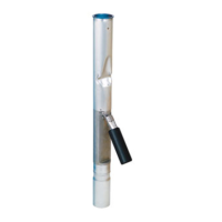
STEP 23: CHECK INSTALLATION
Insert the drop tube all the way into the tank until the
ange and gasket seat onto the top of the Face Seal
Adaptor. The oat will swing out into the operating
position as it passes into the tank.
Make sure that the oat is aligned along the length of
the tank. The length of the tank can easily be deter-
mined by locating other manholes or pump boxes that
are installed around other tank ttings. Look into the
drop tube and align the deector with the length of the
tank.
For testable models only: Unthread the socket adap-
tor assembly from the inlet tube (a 3/8” square drive
extension will attach to the socket adaptor, secure all
tools to ensure they don’t fall into the tank or valve) and
ensure oat and poppet move freely when socket adap-
tor assembly is pulled on. When looking down into the
upper tube ensure poppet is visible when socket adap-
tor is pulled and resets properly when socket adaptor is
released. See page 17 for full testing details. If poppet
does not actuate freely take appropriate steps to correct
before proceeding.
CAUTION: No obstruction in the tank can be within
14" from the center of the riser pipe or the valve
may not operate properly (See Figure 24).
STEP 24: ALIGN VALVE
Install the OPW Jack Screw Kit and a 4" NPT nipple to
lock the valve in place. Refer to the Installation Instruc-
tions supplied with the Jack Screw Kit. For testable
models ensure that the socket adaptor is aligned so
it does not interfere with the jack screw kit. (see Fig-
ure 24A). Install the Rotatable Product Adaptor (Refer
to Installation Instructions supplied with the Product
Adaptor.) Make sure that the valve does not rotate
while tightening the adaptor by observing the position
of the deector. The valve must remain aligned
along the length of the tank as in Step 23. Repeat
this step as necessary to assure proper valve alignment.
Figure 22
Figure 23
 Loading...