23
Appendix C
HOW TO LOCATE THE POSITION OF THE 71SO FOR COMPLETE SHUT-OFF AT A GIVEN TANK CAPACITY
Note: This Appendix only applies when AHJ require-
ments call for complete shut-o at a given tank capacity.
See page 4 for standard measurements.
The length of the upper tube and the placement of the
71SO valve body determine the shut-o point. The sam-
ple calculation below will provide for complete shut-o
at 95%. In all cases, the upper tube length must be a
minimum of 6-1/2" plus the length of the riser pipe. All
length measurements are in inches.
INSTRUCTIONS
1. Find the tank capacity (in gallons) from the tank cali-
bration chart provided by the tank manufacturer.
2. Calculate 95% of capacity.
3. Locate the 95% volume number on the tank calibra-
tion chart.
4. Find the dipstick number (X) which corresponds to
the 95% tank volume. And, nd the dipstick number
(Y) which corresponds to the 100% volume.
5. Subtract the dipstick number (X) from the tank diam-
eter (Y) to nd the upper tube reference number (Z).
(Y) - (X) = (Z)
6. Add 1.5" to (Z) to nd the upper tube depth E.
(Z) + 1.5” = E
7. Is E less than 6-1/2"?
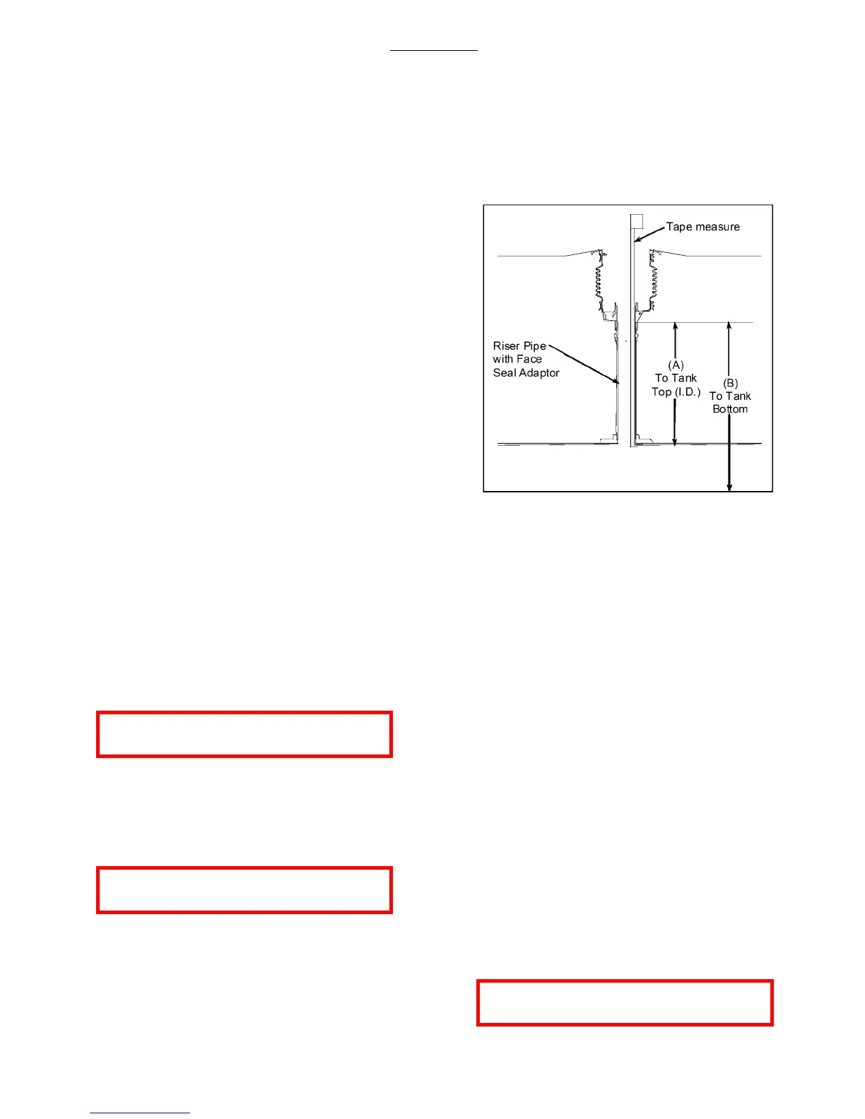
NO Upper tube length is E plus the distance from the
top of the Face Seal Adaptor installed on the riser
pipe to the inside, top lip of the storage tank (A).
Upper Tube Length = E + (A)
For testable models only, ending in “T”:
Upper Tube Length = E + (A) – 1-1/2”
YES Upper tube length is 6-1/2" plus the riser pipe
measurement (A).
Upper Tube Length = 6-1/2" + (A)
For testable models only, ending in “T”:
Upper Tube Length = 6-1/2" + (A) – 1-1/2”
NOTE: You must nd the actual tank capacity num-
ber that correlates to the 6-1/2” + (A) depth for the
station records. This number may also be used or
the purposes of calibrating an electronic tank level
system.
EXAMPLE
1. For an Owens-Corning Model G-3 Fiberglass® Tank
Calibration Chart:
Tank Capacity - 10,000 gal., nominal 9,403 gal.
NOTE: Use actual capacity only
2. 95% of actual tank capacity = 0.95 x 9403 gal. =
8933 gal.
3. The closest number which is less than 8933 gal. Is
8910 gal. Choosing the closest number less than
95% of actual capacity ensures that complete
shuto will occur when the tank is no more than
95% full.
4. The calibration chart reading of 8910 gal. corre-
sponds to a dipstick measurement of 82".
5. Dipstick number (X) = 82"
Tank diameter (Y) = 92"
(Y) - (X) = (Z) (92 "- 82" = 10")
(Z) = 10"
6. (Z) + 1.5" = E (10" + 1.5" = 11.5")
E = 11.5"
7. Is 11.5" less than 6-1/2"?
NO Measure the distance from the top of the FSA-400
Face Seal Adaptor installed on the riser pipe to
the inside, top lip of the storage tank and obtain
measurement (A).
Upper tube length = E + (A)
For testable models only, ending in “T”:
Upper Tube Length = E + (A) – 1-1/2”
 Loading...