24
Appendix C (continued)
71SO Overll Valve in Tank Complete Shut O Level Worksheet
Important: This is meant to be supplemental worksheet and not a substitute to following the installation
manual instructions. All length measurements are in inches. Please contact the Authority Having Jurisdic-
tion (AHJ) and review local, state, and national codes to determine the regulatory requirements governing
shut-o capacity in your region, as well as take into account other considerations such as extreme tank tilt.
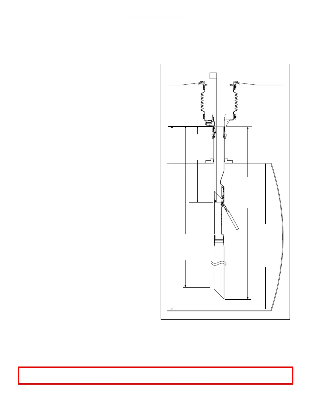
Take the following measurements with the valve in-
stalled in the tank:
Distance from the 71SO inlet tube ange to the cast
lug in the 71SO body (see gures), upper tube length.
Note: the Upper Tube Length must be at least 16” to in-
clude the protective bend in the tube.
(D) = ______________________
Distance from the 71SO inlet tube ange to the top and
bottom of lower tube, valve length.
(W) = _____________
(U) = _____________
Distance from the 71SO inlet tube ange to the bottom
of the tank. Note: If a tank bottom protector is present it
may be necessary to add this thickness to dimension
(OPW 6111 & 61TP models add 0.6”)
(B) = _____________
From the tank calibration chart provided by tank manu-
facturer nd the dipstick number (Y) which corresponds
to the 100% volume.
(Y) = _____________
1. To determine complete shut-o percentage:
Subtract upper tube length (D) from distance to tank
bottom (B)
(X) = (B) – (D) + 1.5” =________________________
Using the tank calibration chart provided by the tank
manufacturer determine the tank capacity at the cal-
culated (X) dimension and the 100% volume (Y) tank
capacity.
(X) tank capacity in gallons = _______________
(Y) tank capacity in gallons = _______________
Complete SO% = (X) capacity / (Y) capacity x100 =
__________
Note: The overll valve must be installed per AHJ re-
quirements and all applicable local, state, and national
codes. If the overll valve is set above the allowable
shut-o percentage the overll valve must be removed
and replaced.
(B)
To Tank
(D)
Upper
Tube
(W) Valve
Length,
bottom
of cut
(Y)
Tank
Chart
100%
Volume
Dipstick
(U) Valve
Length,
top of
Note: This Appendix only applies to valves installed per Appendix C. See Appendix B for the standard valve
installation tank shut o level worksheet.
 Loading...