3
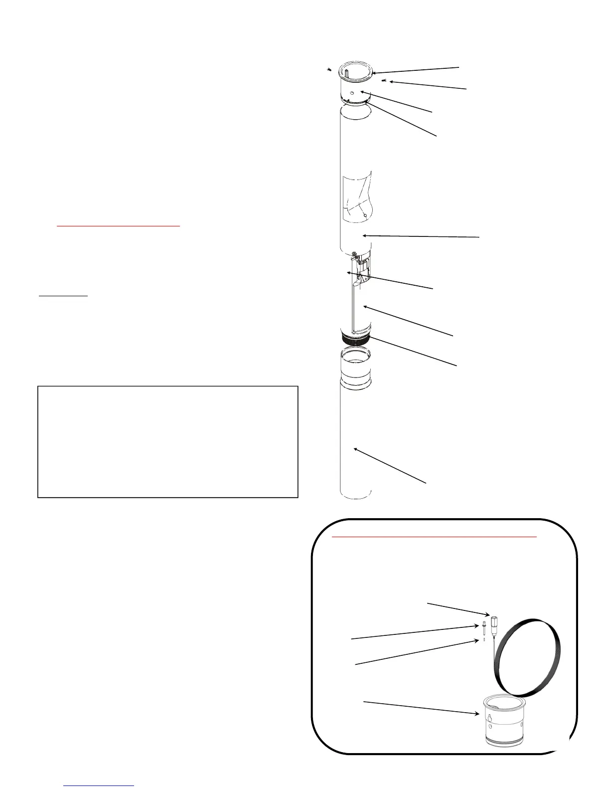
Alternate Components - Testable Versions
Note: all components are the same except the
socket adaptor & cable assembly, rivet, testable
inlet tube, and ferrule.
Rivet
Ferrule
Testable Inlet
Tube
Socket Adaptor & Cable
Assembly
2. Drill
3. Hammer
4. Tape measure
5. Hacksaw or cut-o saw, ne tooth; 24 teeth/inch
6. Fine half round le
7. Screwdriver - Phillips blade
8. Fine grit sandpaper / steel wool
9. Grease, black moly
10. Torque Wrench
11. Band clamp (3-3/4” diameter minimum)
12. TESTABLE MODELS ONLY: rivet tool for 1/8” man-
drel, crimping tool / pliers, wire cutter / scissors,
pipe dope, 1/4” square drive extension or 3/8”
square drive extension with 3/8” to 1/4” socket
adapter.
WARNING
Using electrically operated equipment near gasoline
or gasoline vapors may result in re or explosion,
causing personal injury and property damage.
Check to assure the working area is free from such
hazards, and always use proper precautions.
IMPORTANT: The gures in this installation and
maintenance instruction may contain vapor recovery
equipment (including model numbers) that is not certi-
ed by the California Air Resources Board (CARB) for a
specic Phase I Vapor Recovery System. Please refer to
Exhibit 1 of the appropriate CARB Phase I Executive Or-
der for a list of certied Phase I Vapor Recovery System
Equipment.
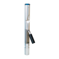
Valve Body
Lower Tube
71SO Parts Diagram
Upper O-Ring Gasket
Screws, Qty 3
Inlet Tube
Polypak Seal
Upper Drop Tube
Float
Lower O-Ring
 Loading...