4
IMPORTANT: The instructions below for the 71SO
Overll Prevention Valve are written for the initial
stage shuto at 95%, but can be adjusted to shuto
at any desired tank capacity. Please contact the Au-
thority Having Jurisdiction (AHJ) and review local,
state, and national codes to determine the regulato-
ry requirements governing shut-o capacity in your
region, as well as take into account other considera-
tions such as extreme tank tilt. In all cases, the up-
per tube must protrude into the tank at least 6 1/2”
to ensure that the valve can shut o ow into the
tank completely before the top of the tank is wetted
as per EPA requirements.
HOW TO LOCATE THE POSITION OF THE 71SO AT
95% TANK CAPACITY
(Shut-o points can be adjusted to any capacity to
comply with AHJ Requirements)
The length of the upper tube and the placement of the
71SO valve body determine the shut-o point. Follow-
ing the standard instructions for the OPW 71SO will pro-
vide for initial shuto at 95%. In all cases, the upper
tube length must be a minimum of 6-1/2" plus the
length of the riser pipe. All length measurements are in
inches.
INSTRUCTIONS
1) Find tank capacity (in gallons) from tank calibration
chart provided by tank manufacturer.
2) Calculate 95% of capacity
3) Locate the 95% volume number on the tank calibra-
tion chart.
4) Find the dipstick number (X) which corresponds to
the 95% tank volume. And, nd the dipstick num-
ber (Y) which corresponds to the 100% volume.
5) Subtract the dipstick number (X) from the tank di-
ameter (Y) to nd the upper tube reference number
(Z).
(Y) - (X) = (Z)
6) Subtract 2" from (Z) to nd the upper tube depth
(C).
(Z) - 2" = C
7) Is C less than 6-1/2"?
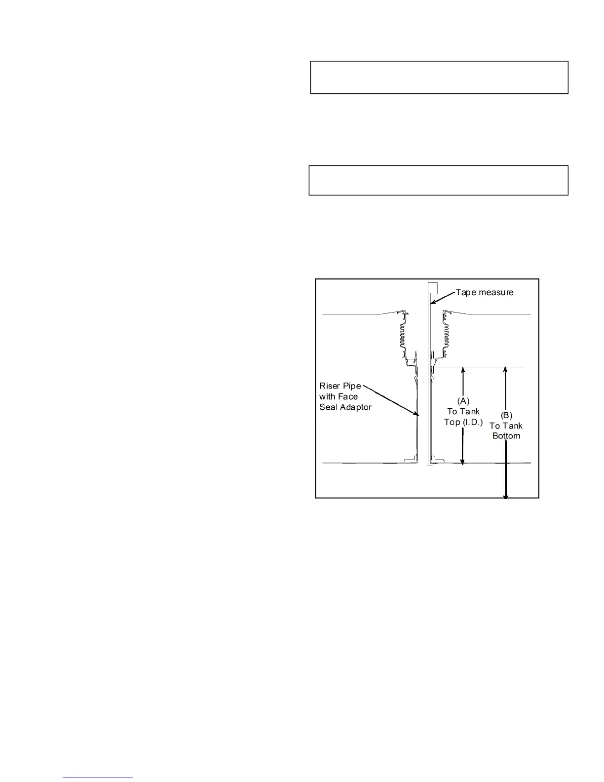
NO Upper tube length is C plus the distance from
the top of the Face Seal Adaptor installed on
the riser pipe to the inside, top lip of the storage
tank (A).
Upper Tube Length = C + (A)
For testable models only, ending in “T”:
Upper Tube Length = C + (A) – 1-1/2”
YES Upper tube length is 6-1/2” plus the riser pipe
measurement (A).
Upper Tube Length = 6-1/2” + (A)
For testable models only, ending in “T”:
Upper Tube Length = 6-1/2” + (A) - 1-1/2”
NOTE: You must nd the actual tank capacity num-
ber that correlates to the 6-1/2” + (A) depth for the
station records. This number may also be used for
the purposes of calibrating an electronic tank level
system.
Figure 1
EXAMPLE
1) For an Owens-Corning Model G-3 Fiberglass® Tank
Calibration Chart:
Tank Capacity - 10,000 gal., nominal 9,403 gal.
NOTE: Use actual capacity only
2) 95% of actual tank capacity = 0.95 x 9403 gal. =
8933 gal.
3) The closest number which is less than 8933 gal. Is
8910 gal. Choosing the closest number less than
95% of actual capacity ensures that the initial
shuto will occur when the tank is no more than
95% full.
4) The calibration chart reading of 8910 gal. corre-
sponds to a dipstick measurement of 82”.
 Loading...