5
5) Dipstick number (X) = 82”
Tank diameter (Y) = 92”
(Y) - (X) = (Z) (92” - 82” = 10”)
(Z) = 10”
6) (Z) - 2” = C (10” - 2” = 8”)
C=8”
7) Is 8” less than 6-1/2”?
NO Measure the distance from the top of the FSA-
400 Face Seal Adaptor installed on the riser pipe
to the inside, top lip of the storage tank and ob-
tain measurement (A).
Upper tube length = C + (A)
For testable models only, ending in “T”: Upper Tube
Length = C + (A) - 1-1/2”
ASSEMBLY INSTRUCTIONS
IMPORTANT: Each of the numbered steps in the instal-
lation instructions are designed as a CHECK LIST to en-
sure proper installation and trouble free operation of
the OPW 71SO Overll Prevention Valve.
Read and follow these steps carefully, checking them
o as you proceed.
Figure numbers correspond to step numbers for easy
reference.
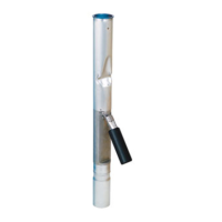
STEP 1: MEASURE
Install the OPW Face Seal Adaptor and the OPW Thread-
on Spill Container on the Fill Riser (Refer to the Installa-
tion Instructions Supplied with the Spill Container). In-
sert a tape measure through the riser pipe and hook it
under the inside of the tank in the lengthwise direction.
Measure the distance from the top of the Face Seal
Adaptor threads inside the base of the spill container
bucket just below the drain valve outlet window to the
inside, top lip of the storage tank (Dim. “A”) (See Figure
1 &1A).
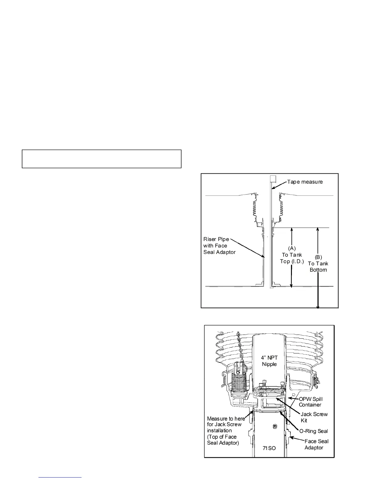
The top ange on the 71SO will rest on the Face Seal
Adaptor just below the drain valve outlet, and be
locked in place between the Face Seal Adaptor and the
4" nipple that is installed in the spill container with the
Jack Screw Kit (See Figure 1A). (For riser pipe congu-
rations other than that shown, consult installation
drawings or use other necessary means to measure Di-
mension “A”).
Using a tape measure, measure the distance from the
top of the Face Seal Adaptor in the spill container to the
bottom of the tank (Dim. “B”).
IMPORTANT: Inspect the riser pipe for any foreign ma-
terial. Over spray from tank relining or any internal
burrs inside of pipe must be removed prior to installa-
tion. Failure to have an unobstructed riser pipe may
prevent proper installation and operation of the valve.
The 71SO is designed for installation into schedule 40
riser pipes. The 71SO cannot be installed into schedule
80 riser pipes.
STEP 2: MARK THE TUBE
Use the result from Step 1 and HOW TO LOCATE THE
POSITION OF THE 71SO AT 95% TANK CAPACITY to
mark the upper tube. Measure the distance from the
seam where the upper tube and valve body meet. Use
a tape measure to mark the calculated upper tube
length onto the upper tube. See Figure 2.
Figure 1
Figure 1A
 Loading...