 Loading...
Do you have a question about the ORANGE OR50 and is the answer not in the manual?
| Power Output | 50 Watts |
|---|---|
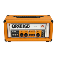
| Inputs | 1 x 1/4" Instrument Input |
| Type | Valve/Tube Amplifier |
| Controls | Volume, Bass, Middle, Treble |
| Tubes | 3 x ECC83 |
| Impedance | 8 Ohms |
| Outputs | Speaker Outputs: 1 x 16 Ohm, 2 x 8 Ohm |
| Dimensions | 55 x 27 x 28 cm |