EasyManua.ls Logo

OrangeRx RX3S User Manual

Default Icon
4 pages
To Next Page IconTo Next Page
Page #1 background imageLoading...
Page #1 background image
!"#$%&'() *+,-./) 01.%23) 43#5.1.6&") 7*) 8.32) 49&:3";<=>')
?4@A)BC<9#3.51&)DB2)AEFGH6)'&I&.J&")K7+3#.1=?&13#=,L(M)
N#OC;3P)
!
"#$!%&&!'$(!)*+,!-.%'/$)*!0&1/#2!,2%31&14$.!5+!(12#!,6$72.89:;)!<,=>!?@96%213&$!A?#!>BCDE4!)$F$1G$.!
%HHI!I866@.2!J@.!5K2%1&!L!<$&2%!9@H$&IM!12!%&I@!@JJ$.I!%!.$9@2$!-N:-00!J$%28.$!2#%2!F%'!3$!F@'2.@&&$H!G1%!
O@8.!2.%'I9122$.PI!QR*!F#%''$&B! !
!
R21&141'/!%!I1'/&$!#1/#!6.$F1I1@'! +K%S1I!=T=,!/O.@M!2# $!)*+,!-.%'/$)*!0& 1/#2!,2%31&14$.!5+!(12#!,6$72.89:;)!
<,=>!?@96%21%&$!A?#!>BCDE4!)$F$1G$.!1I!F%6%3&$!@J!I2%31&141'/!J&1/#2!@'!U8I2!%3@82!%'O!J1S$H!(1'/!%1.F.%J2V!
W2!6.@G1H$I!%HH$H!I2%31&12O!3O!%82@9%21F%&&O!F@..$F21'/!2#$!%1&$.@'M!$&$G%2@.!%'H!.8HH$.!F#%''$&I!1'!J&1/#2B!
"#1I!F@96$'I%2$I!J@.!8'(%'2$H!F#%'/$I!1'!2#$!%1.6&%'$PI!%22128H$!H8$!2@!(1'H!%'H!@2#$.!J%F2@.IB!W'!I#@.2M!
12!9%7$I!O@8.!%1.6&%'$!98F#!9@.$!I2%3&$!1'!J&1/#2V! !
!
"#$!)*+,!5+!(12#!,6$72.89:;)!<,=>!?@96%213&$!A?#! >B CDE4!)$F$1G$.!1I!/.$%2!J@.!2#@I$!(#@!2$'H!2@!J&O!1'!
(1'HO!F@'H121@'IM!%I!12!(1&&!F@96$'I%2$!J@.!(1'H!/8I2I!2#%2!(@8&H!'@.9%&&O!68I#!O@8.!9@H$&!%.@8'HB!W2PI!
%&I@!%'!1H$%&!%HHK@'!2@!O@8.!J%G@.12$!0X5!9@H$&!2@!7$$6!12!@'!2#$!I2.%1/#2!%'H!&$G$&!(#1&$!J&O1'/B!
!
"#1I! 8'12! 1I! G$.O! I196&$! 2@! 1'I2%&&! %'H! 8I$B! "#$! %HU8I2%3&$! /%1'! I$221'/I! %.$! 6.$KI$2! 2@! YZ[! @JJ$.1'/! 91&H!
I2%31&14%21@'B! \@8! F%'! $%I1&O! %HU8I2! 2#$! /%1'! J@.! $%F#! F#%''$&! %I! H$I1.$H! 2@! 1'F.$%I$! @.! H$F.$%I$! 2#$!
F@96$'I%21@'!J@.!2#$!.$I6$F21G$!F#%''$&!]QW^M!T^TM!)R<_B!
Question and Answer IconNeed help?

Do you have a question about the OrangeRx RX3S and is the answer not in the manual?

OrangeRx RX3S Specifications

General IconGeneral
BrandOrangeRx
ModelRX3S
CategoryController
LanguageEnglish

Summary

Layout and Outputs

Output Channels

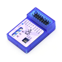
Lists the output channels for the flight stabilizer, including AUX, GEAR, AIL, RUD, ELE, THR, and BATT.

Installation and Binding

Mounting and Orientation

Instructions on using double-sided tape, correct fuselage placement, and antenna orientation for optimal performance.

Binding Procedure

Steps for putting the unit into bind mode and preparing it for binding to a transmitter.

Wiring and Controls

Servo and Power Wiring

Details on connecting servos (AIL, ELE, RUD) and power wires, including color coding and pin orientation.

Gyro Gain Adjustment

Instructions on using potentiometers to adjust roll, pitch, and yaw gyro gain for optimal stabilization.

6-Position Switch Controls

Explains the function of six DIP switches for controlling gyro modes, reversing servo directions, and selecting aircraft types.

Initial Setup and Testing

Pre-flight Checks

Guidance on checking channel connections, transmitter controls, LED indications, and signal output before flight.

Gyro Signal Output Testing

Demonstrates how to test and set the direction of gyro response for roll, pitch, and yaw axes using visual examples.

Related product manuals