8)
OPTIONAL
verification of LIN
and EXP release
a) Connect
the vertical input of
a storage
scope to the
rear-panel
STEREO
COUPLE
terminal.
This
monitors the gain
of the VCA,
and
is scaled such
that
each dB of gain reduction
changes
the voltage by -0.4V.
b) Operate
the
scope at
IV/div vertical
and approximately 0.2sec/div
horizontal. Switch the RELEASE SHAPE switch to LIN and
make sure that
the
GATE
THRESH is
OFF. Apply
a level from
the
oscillator to the
424A
input
terminals sufficient to make the 424A G/R
meter
read
"20dB".
This
should
produce a
voltage
at
the
STEREO COUPLE terminal of approximately
-8.0V.
c) Suppress
the oscillator output,
and
observe the
control
voltage with the scope
as
it
releases. It should create a straight line until -0.3V
has
been reached,
at
which point
the
line
will become much
more horizontal. Do not
erase the
trace; it will be superimposed with another trace in the next
step.
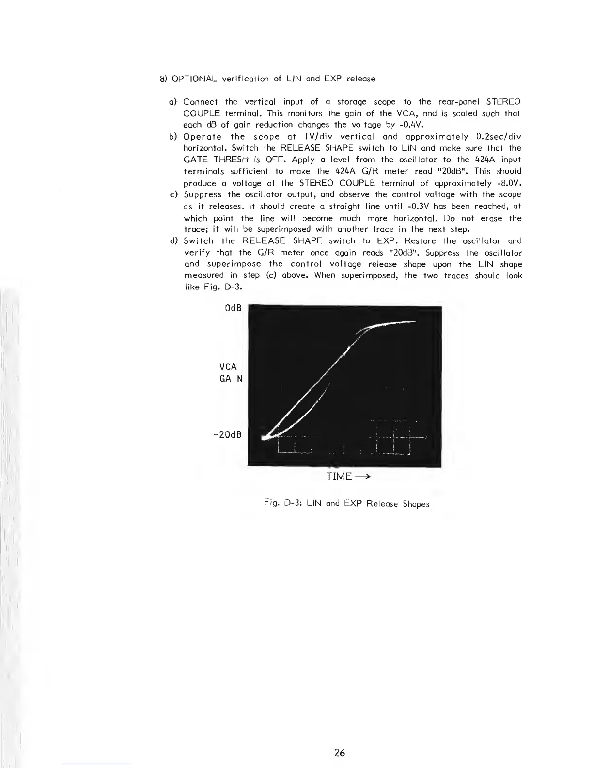
d) Switch the
RELEASE
SHAPE switch
to
EXP. Restore the oscillator
and
verify that the
G/R
meter once
again reads "20dB".
Suppress the oscillator
and superimpose the control voltage
release shape
upon
the
LIN shape
measured in
step
(c) above. When
superimposed,
the
two traces should look
like Fig. D-3.
OdB
VCA
GAIN
-20dB
TIME—
>
Fig.
D-3: LIN
and EXP
Release
Shapes
26