14
Station Delay
This feature is commonly used by homeowners with cisterns or well
water. The delay allows cisterns and wells adequate time to re-supply
the reservoir.
Note: Delays between stations can be programmed from 1 minute to 9 hours.
TO PROGRAM STATION DELAY:
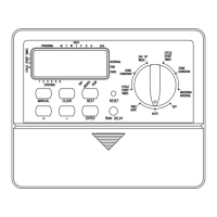
1. Turn the rotary dial to •STATION DELAY [See Figure 22]
2. To increase or decrease the time delay time between each station,
press the
+ or – button.
3. Press the ENTER button to save the time delay setting.
4. Return the rotary dial to AUTO
Section 7: Installation of Indoor Mount
Sprinkler Timer
Before installation please have the following items and tools.
• 2 AA Batteries
• Phillips Screwdriver
• Wire Strippers
Installing the sprinkler timer in 5 easy steps
1. Selecting a Location
2. Mounting the Sprinkler Timer
3. Installing the Batteries
4. Connecting the Power Supply
5. Connecting Valve Wires to Sprinkler Timer
Note: For installation of OUTDOOR models see Appendix A
1. Selecting a Location
Select a location with the following criteria:
• Near an electrical outlet (Avoid using an outlet controlled by
a switch)
• An indoor, dry location, where operating temperatures are not
below 32° or above 158° Fahrenheit (0 degrees or above 70
degrees Celsius)
• Avoid direct sunlight
• Access to sprinkler wire (from valves)
2. Mounting the Sprinkler Timer
• Using the mounting template (included) mark the screw
locations on the wall.
• Insert a No. 8 screw (included) in the upper mark, leaving the
screw head about 1/8th (3mm) out from the wall. (Use the
expanding anchors in plaster or masonry if necessary.)
• Slip the keyhole slot in the back of the sprinkler timer over the
extended screw.
[See Figure 23]
• Screw a No. 8 screw through the two holes located behind the
batteries in the battery compartment.
3. Install the Batteries
Two AA alkaline batteries are required to retain the program in memory
during power loss. Annual replacement is recommended.
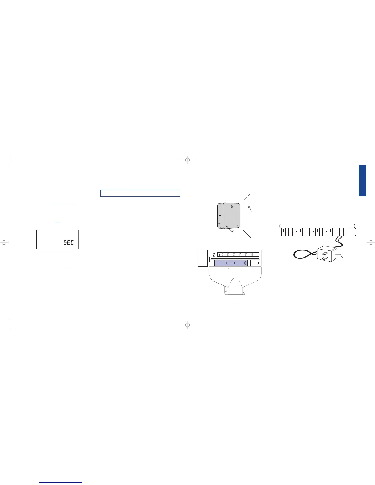
• Remove the battery cover by sliding it to the left.
[See Figure 24]
• Insert two AA alkaline batteries
Figure 22: Display – Station Delay
• Replace the battery cover
Note: Batteries alone will not operate the valves in your sprinkling system.
The 24-volt transformer must be plugged in and have power to operate
your system normally.
4. Connecting the Transformer
• With the cover off, find the two terminal holes labeled
“24VAC IN” [See Figure 25]
• Insuring the transformer is not plugged in; insert one of two
power leads (from the transformer) into each terminal.
Note: It may be necessary to open the terminal to allow for wire insertion
or removal. This is done by pressing upward on the tab located on top of
the terminal.
• Plug in the transformer.
Warning: Do not link two or more sprinkler timers together with
one transformer.
Section 8: Wiring Valves, Sprinkler Timer,
Pump Start and Master Valves
1. Wiring the Electric Valves
Note: If the distance between the sprinkler timer and valves is under 700'
(210 m), use Orbit
®
sprinkler wire or 20 gauge (AWG) plastic jacketed
thermostat wire to connect the sprinkler timer to the valves. If the distance
is over 700' (210 m), use 16 gauge (AWG) wire.
Figure 24: Battery Compartment
Figure 23: Mounting the Sprinkler Timer