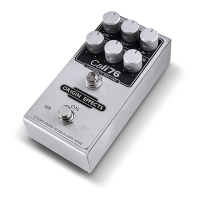
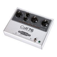
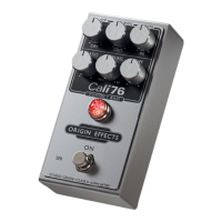
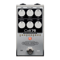
Input/Comp Control
The Cali76 features a very nice studio-grade input
preamplifier. This works as an interface between the guitar
and the compressor sections. In exactly the same way a
studio-engineer will first amplify a dry guitar signal before
applying additional processing.
The "INPUT/COMP" control allows the user to vary the gain of
this preamplifier. Turning this control clockwise increases the
overall gain of the pedal. This also increases the amount of
compression. The guitar will become increasingly more touch-
sensitive. Too much gain and the preamplifier will clip and
distort.
Compression is greatly reduced at lower gain settings as much
of the signal entering the compressor section falls below the
compressor's internal threshold. Signal level must exceed this
threshold in order to initiate gain-reduction. In this scenario
only the signal-peaks are compressed.
Output
The Output control simply varies the level of signal present at
the pedal's output jack. This can be set in order to keep the
overall effected-level close to the, dry (bypass) signal.
Alternatively, the level can be increased to help project a
guitar solo.
Attack & Release
Attack & Release controls are all too often misunderstood,
which is unfortunate as they are instrumental in achieving a
usable sound. In most cases Attack & Release parameters
should be adjusted to optimise the compressor's dynamic
response to that of a particular instrument. However, they can
also be adjusted to create strong dynamic effects.
The Attack control determines the time taken for the
compressor to react to the presence of a signal, i.e. the delay
from the instant when you play the note, to the moment the
compressor actually reduces the gain. The longer the Attack-
time/delay, the more pronounced the beginning of each note
will sound.
In the context of the guitar - you may make the following
observations when adjusting Attack settings:
Increasing Attack-time highlights the percussive "snap" of
strongly picked notes.
Reducing Attack-time may impart a "spongy" feel to the
character of the compressor - especially when "digging-in" to
single notes!
Reducing the Attack-time to a very short time will result in
undesirable distortion being generated - this will be heard to a
greater extent when playing bass notes.
The Release control determines the duration of any gain
reduction. This would be measured from the time that
compression is triggered to the point that the compressor has
returned to its idle state. For maximum effect when processing
guitar, the Release must be set so that the compressor
responds fully to every note played. If so, the release time
must be short enough for the compressor to fully recover in the
short time between one note ending and the next note
beginning.
Ratio
The Ratio control allows the user to adjust the amount of gain
reduction applied for any given increase in guitar signal. At
the lowest ratio-setting, doubling the input signal (an increase
of 100%) will result in the output increasing by 19%. At the
highest ratio-setting, the output would rise by only 3.5%, for
the same increase in input signal. The latter case represents
"Limiting".
As was the case in the Urei 1176, changing the ratio setting
also varies the threshold level of the unit. This helps to keep
the output at a consistent level, regardless of settings.
Example Settings
Figure 1 presents some useful starting points, intended for use
with guitar. Figure 5 consists of some more examples for use
in processing various recorded instruments.
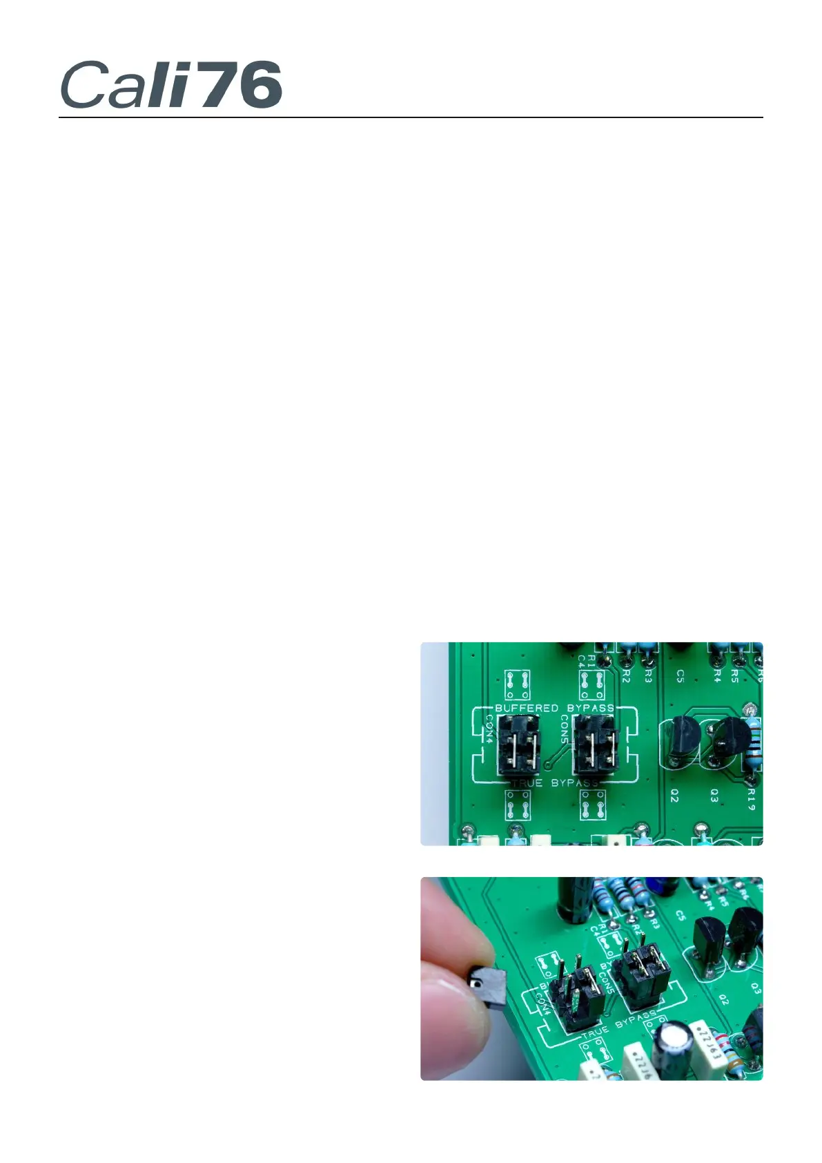
Bypass Mode (Internal Selection)
The bypass mode can be selected internally by changing the
positions of four internal jumper-connectors.
"True-Bypass" can be obtained with all four jumpers in the
lower-position.
A low impedance, or buffered-bypass, mode can be selected by
moving all four jumpers to the upper-position. In this mode,
the pedal will ensure that signal integrety is preserved even
when driving long cable runs.
Jumpers can be simply pulled away and pushed back into
place. Spare jumpers can be easily obtained if required.
Figure 2: J4, J5, J6, J7: Bypass Jumper-Connectors.
Figure 3: Changing the jumper position on J4.
 Loading...