4
Instructions for Electric Burners
Never attempt to use electric and alcohol burners simultane-
ously. To do so will cause overheating, which can destroy the
electric elements.
• Move cutting board away or open the glass top as applica-
ble to your unit.
• Turn switch on to desired setting (symbol on the stove
indicates which switch to use).
• Turn switch off when cooking is complete.
• Make sure that the elements have cooled down completely
before replacing the cutting board or glass top.
• Disconnect switch should be in off position when stove is
not in use.
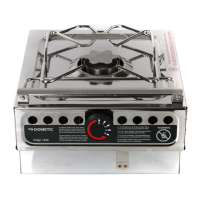
Electronic Burner Control
The power is varied in 5 steps. There is also a zero/off
position and a key button. Shutting the lid or the cutting
board will shut off electric power, as a safety only. Turn
off burner and allow it to cool before closing glass lid or
replacing cutting board. Glass lid is not a cooking sur-
face. The selection of the desired power level is done by
push buttons for each burner (one burner at ORIGO 2500
E) labeled (+) = ”step up” and (-) = ”step down” respec-
tively.
The present power level is indicated by 3 light emitting
diodes (LEDS) for each burner in a combination fashion.
The indications are as follows in the ascending order:
Off Position
Power level 100%
Please notice.
To start the stove, you have to push the key button
and within 10 seconds the (+) button.
After using the off button, you have to use the key
button to restart the stove again.
Holding the buttons (+) or (-) down will repeatedly step
the power up or down respectively until hitting the end
position i. e. full power and off positions respectively. A
single brief push will change only one step in the desired
direction. The off button operated by the lid will shut
both electric burners off.
INSTALLATION.
Fitting of the Stove.
Your stove should be located in a well-ventilated space. Avoid
excessive draft. If you fit in an open cockpit, or other open
area, wind protection must be provided.
Cut a rectangular hole (see measurements below). Place the
stove (with the top open and tanks removed) in the middle of
the hole. When in proper position, use the fastening holes in
the rim as a template to mark and drill for B-10 screws with
low heads to clear the stovetop. Install the screws and fasten
securely.
WARNING!
PLACE UNIT IN A WELL-VENTILATED AREA
AWAY FROM ALL COMBUSTIBLE MATERIALS.
INSTALL A CLASS B-1 FIRE EXTINGUISHER
IMMEDIATELY AT HAND.
The stove shall be installed in accordance with national regula-
tions. In USA it is advisable to follow the ABYC recommenda-
tions.
Cutout for Model No:
2000 and 2500: 13 5/8” x 12 13/16” (345 x 325 mm)
4000: 20 1/2” x 12 1/4” (520 x 310 mm)
4100 and 4300: 22 5/8” x 12 13/16” (575 x 325 mm)
The appliance must be connected only to the current marked on
the stove.
Use No. 12, three-wire tp. SO rubber insulated cable. Black L1
wire to be ungrounded conductor. Secure the cable with the
clamp.
(See applicable USCG or ABYC requirements)
Technical Data.
For Model No. 2000 and 2500:
Height: approx. 6 ” (150 mm)
Depth: approx. 14 7/8” (377 mm)
Length: approx. 15 5/8” (396 mm)
For Model No. 4000:
Height: approx. 6” (150 mm)
Depth: approx. 14 3/16” (360 mm)
Length: approx. 22 1/2” (620 mm)
For Model No. 4100 and 4300:
Height: approx. 6” (150 mm)
Depth: approx. 14 7/8” (377 mm)
Length: approx. 24 1/2” (623 mm)
Tank Volumes: approx. 2,5 pints each (1,2 L)
Fuel: Denatured alcohol, Methylated spirit
Coil elements: 1100 W each
ORIGO AB SWEDEN
1540 Northgate Blvd.
SARASOTA, Florida 34234
USA
Phone (941) 355 4488
Fax (941) 355 1558
Manufactured by
DOMETIC ORIGO AB
Fax +46 35 165710
Phone +46 35 165700
Söndrumsv. 35, SE-302 39 Halmstad
Sweden
VREDBAND IMPORT INC.
1855 A, Boul. Industriel
Chomedey, Laval Qc. H7S 1P5
CANADA
Phone (450) 668 3111
Fax (450) 668 6270
 Loading...