Do you have a question about the Orwak 9020 and is the answer not in the manual?
Details the machine's built-in safety mechanisms and protective features.
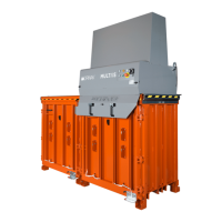
Details intended use, materials, and operating environment.
Guidance on fire extinguishing and environmental protection.
Procedures for scrapping and disposing of the machine.
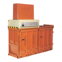
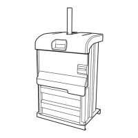
Identifies and illustrates front machine components.
Identifies and illustrates rear machine components.
Explains function of buttons, indicators, and displays on the control panel.
Provides guidance on identifying and resolving common operational faults.
Detailed steps for correctly securing bales with straps.
Instructions for loading material and initiating the compaction cycle.
Detailed steps for safely and efficiently removing the compacted bale.
Routine checks and maintenance tasks for machine safety and performance.
Procedure for cleaning the press plate after use.
Steps for monitoring the hydraulic oil level.
Guidance on lubricating the machine's chamber.
A list of critical safety checks to perform on the machine.
Provides overall weight, chamber, and press unit details.
Illustrates the machine's dimensions with labels.
Details electrical requirements for 50Hz and 60Hz operation.
Information and illustrations for transporting the machine.
Lists specifications related to the machine's hydraulic system.
Steps for unpacking parts and fitting guards and chambers.
Instructions for qualified electrician connecting the machine to mains power.
Steps for opening covers, connecting components, and performing initial checks.
Instructions for swapping cables and removing internal supports.
Guidance on selecting pressure and fitting the apron.
Steps for positioning, levelling, connecting, and testing the machine.
Filters hydraulic fluid intake.
Motor driving the hydraulic pump.
Pressurizes hydraulic fluid.
Allows fluid flow in one direction.
Port for testing hydraulic pressure.
Controls hydraulic fluid flow direction.
Prevents over-pressurization and manages regenerative flow.
Check valve controlled by pilot signal.
Connector for hydraulic lines.
Stores hydraulic fluid.
Allows air into reservoir while filtering.
Limits maximum system pressure.
Filters returning hydraulic fluid.
Assembly containing the hydraulic pump.
Electrically operated check valve.
Check valve controlled by pilot signal.
Measures hydraulic system pressure.
Hydraulic actuator performing pressing action.
Protects the hydraulic motor from overload.
Provides voltage for control circuits.
Switches the hydraulic motor on and off.
Details inputs related to machine safety features.
Details outputs related to safety control.
Lists various inputs to the control system.
Specifies analog input signals and connections.
Lists various outputs from the control system.
Shows auxiliary connections like alarm/thermostat signals.
Sensors indicating machine part positions.
Detects presence or absence of objects.
Relay for the rail sensor.
Connection points for main electrical supply.
Wiring details for the hydraulic motor.
Wiring for apron-associated sensors.
Electrical connections for the brake system.
| Brand | Orwak |
|---|---|
| Model | 9020 |
| Category | Industrial Equipment |
| Language | English |