OSAKA - USER MANUAL - B4U - v2 - PAG. 16
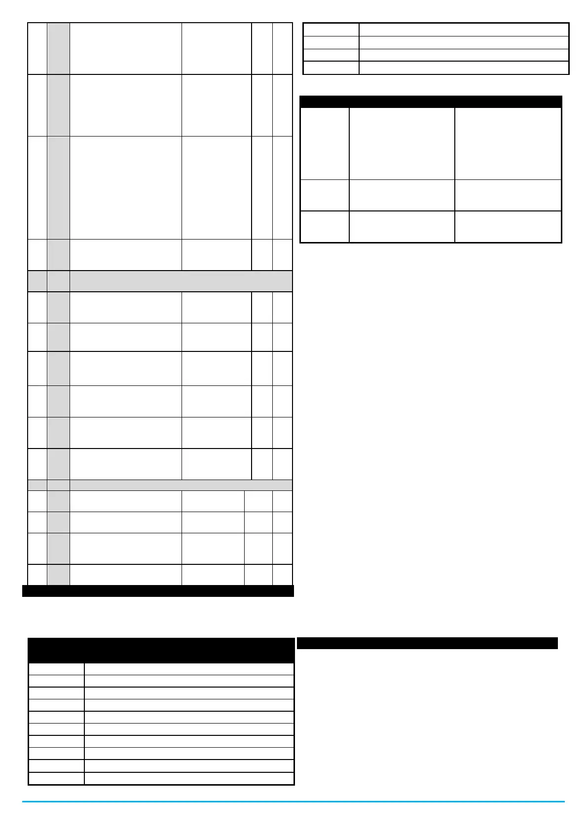
OUT4 output operation
configuration: See “o1”
oF / ot / dF / Fn /
Au / At / AL / An
/ -t / -L / -n / on /
HE / 2d / L1 / L2
/ -d / A2
Buzzer operation
oF = deactivated
1 = for alarm only
2 = keyboard only
3 = activated for alarms
and keypad
Auxiliary output operating
mode
oF = No Function
1 = Output ot delayed
2 = Manual activation of
key or digital input or by
time clock
3 = Manual activation of
the keyboard - digital input
although in Standby
Time relative to auxiliary
output
oF / -01 ÷ -59
(min) ÷ 01 ÷ 99
(hrs)
t. - Parameters related to the keyboard and serial
communication
oF / -01 ÷ -59
(sec) ÷ 01 ÷ 99
(min)
Access password to
operating parameters with
subdivisions into folders
Device address for
MODBUS serial
communication
Temperature display
increment delay filter
Temperature display
decrease delay filter
Time relative to auxiliary
output A2
oF / -01 ÷ -59
(min) ÷ 01 ÷ 99
(hrs)
U. - Parameters related to voltage alarms
oF / -01 ÷ -59
(sec) ÷ 01 ÷
99 (min)
Voltage measurement
calibration
7 - ERRORS, MAINTENANCE AND WARRANTY
7.1 - SIGNALS
7.1.1 - Error messages:
Start-up delay after powering device
Second high temperature alarm
Second Low Temperature Alarm
Digital input alarm in progress
Defrost active, indication if “d.dL” = Lb
Economic modality selected
Low voltage drop alarm in the network.
The relative probe may
be broken (E) or
shorted (-E), or it may
have a value that is
outside the
programmed range.
Check the connection of
the probe with the
device and verify the
correct functioning of
the probe. (it is useful to
have the ohm values of
the probes)
Possible anomaly in the
EEPROM memory
Press the SET key.
Turn the device off and
on
Fatal Device Memory
Error
Replace the device or
send it in for possible
repair
7.2 - CLEANING
It is recommended to clean the B4U only with a cloth slightly
dampened with water or a non-abrasive detergent and that does not
contain solvents.
7.3 - WARRANTY AND REPAIRS
This B4U has a warranty in the form of repair or replacement, for
manufacturing defects in materials, within 12 months from the date
of purchase.
OSAKA SOLUTIONS will automatically void said warranty and will
not
will be liable for possible damages arising from:
The use, installation or improper manipulation or
manipulation other than those described and, in particular,
that differ from the safety prescriptions established by the
regulations.
The use of applications, machines or panels that do not
guarantee adequate protection against liquids, dust, grease
and electric shocks in the assembly conditions carried out.
Inexperienced handling / and / or alteration of the product.
Installation / use in applications, machines or panels that do
not comply with the regulations of the current law.
In the event of a defective product within the warranty period or
outside this period, it is necessary to contact the after-sales service
to carry out the appropriate procedures. Request repair document
"RMA" (by email or FAX) and fill it in. It is necessary to send the RMA
and the B4U to SAT OSAKA freight prepaid.
7.4 - DISPOSAL
The B4U (or the product) must be collected separately in accordance
with current local regulations regarding disposal.
8.1 - ELECTRICAL CHARACTERISTICS
Feeding: 100..240 VAC +/- 10%
AC frequency: 50/60 Hz
Consumption: approximately 4 VA
Tickets: POWER UNIT B4U: 3 inputs for NTC temperature probes
(103AT-2, 10 K Ω at 25 ° C) of which 2 can be digital for power-free
contacts;
DISPLAY B4U: 1 digital input for voltage-free contacts.
Departures: up to 4 relay voltage outputs.
Common power supply (pin 1): 12 A Max.
Electrical life relay outputs: 30K op. according to 60730
Action: type 1.B according to 60730-1
Overvoltage category: II
 Loading...