OSAKA - USER MANUAL - B4U - v2 - PAG. 5
4.1.1 - MECHANICAL DIMENSIONS, DRILLING AND FIXING.
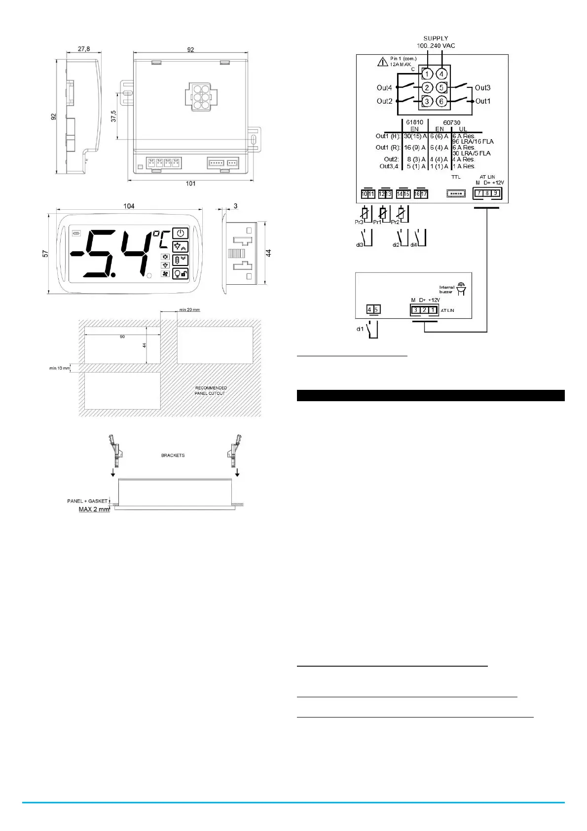
4.2 -ELECTRIC CONNECTIONS
Make the connections by connecting a single conductor per terminal
and following the diagram shown, verifying that the supply voltage is
that indicated on the B4U and that the absorption of the actuators
connected to the B4U is not greater than the maximum allowed
current.
The B4U is designed for permanent connection inside a panel, it is
not equipped with a switch or internal overvoltage protection devices.
Therefore, it is recommended to install a bipolar switch, marked as
the disconnecting device, which interrupts the electrical supply to the
appliance. This switch should be placed as close to the B4U as
possible and in a place that is easily accessible to the user.
Furthermore, it is recommended to adequately protect all circuits
connected to the B4U with devices (eg fuses) suitable for circulating
currents.
It is recommended to use cables with insulation that is appropriate
for the voltages, temperatures and operating conditions, and to
ensure that the cables related to the input sensors are kept away
from the power cables to avoid electromagnetic disturbances. If some
cables used for wiring are shielded, it is recommended to ground
them from one side only.
Before connecting the outputs to the actuators, it is recommended to
verify that the set parameters are the desired ones and that the
application works correctly to avoid anomalies in the system that
could cause damage to people, things or animals.
4.2.1 - ELECTRICAL WIRING DIAGRAM
* Color legend Cable - Strip:
1 - Brown / 2 - White / 3 - Green / 4 - Blue / 5 - Red /
6 - Black.
5.1 - ON / STAND-BY FUNCTION
The B4U, once turned on, can take 2 different conditions:
- ON: It means that it works with the normal control functions.
- STAND-BY: It means that the controller does not operate with any
control function and the display turns off, the Stand-by LED remains
on.
Going from the Stand-By state to the ON state is exactly the same as
turning on the B4U with the power supply.
In case of power failure, the B4U returns to the function that was just
before the power supply interruption.
The ON / Stand-By function can be selected in the following ways:
- Pressing the ON / OFF key for 1 second.
- Through digital input if parameter "1F / 2F / 3F / 4F" = 7.
5.2 -"NORMAL", "ECONOMIC" AND "TURBO" OPERATING
MODE
The B4U allows programming 3 regulation Set Points, one Normal -
"S1", one Economy - "SE" and one "Turbo" - "SH".
Associated with each of them is the relative differential (hysteresis)
normal - "d", Economic - "Ed" and "Turbo" "Hd".
Note: In the following examples, the Set Point is generically indicated
as "SP", in any case, the B4U will act according to the active Set
Point.
OPERATION IN "NORMAL-ECONOMIC MODE"
It can be used if necessary by switching to 2 different operating
temperatures (eg day / night or weekdays / holidays).
NORMAL / ECONOMY mode can be switched manually:
- Through digital input if parameter "1F / 2F / 3F / 4F" = 6
NORMAL / ECONOMY mode can be switched automatically:
- Through a delay time that elapses since the door is closed
(switching from Normal to Economic mode). This time is set in the
"Et" parameter.
- When the door is opened, if the Economic Set Point “SE” is active
(switching from Economic to Normal mode).

 Loading...