Remote Operations
OSA 5240 - User Manual - Revision P - June 2009
7-3
7.1 Features
The OSA 5240 Telecom GPS Receiver features the following remote control/monitoring
capabilities:
• Electrical alarms
(Three relay contacts).
• Local management
via a RS-232C port
• Network Management
via a dedicated Management port (Ethernet).
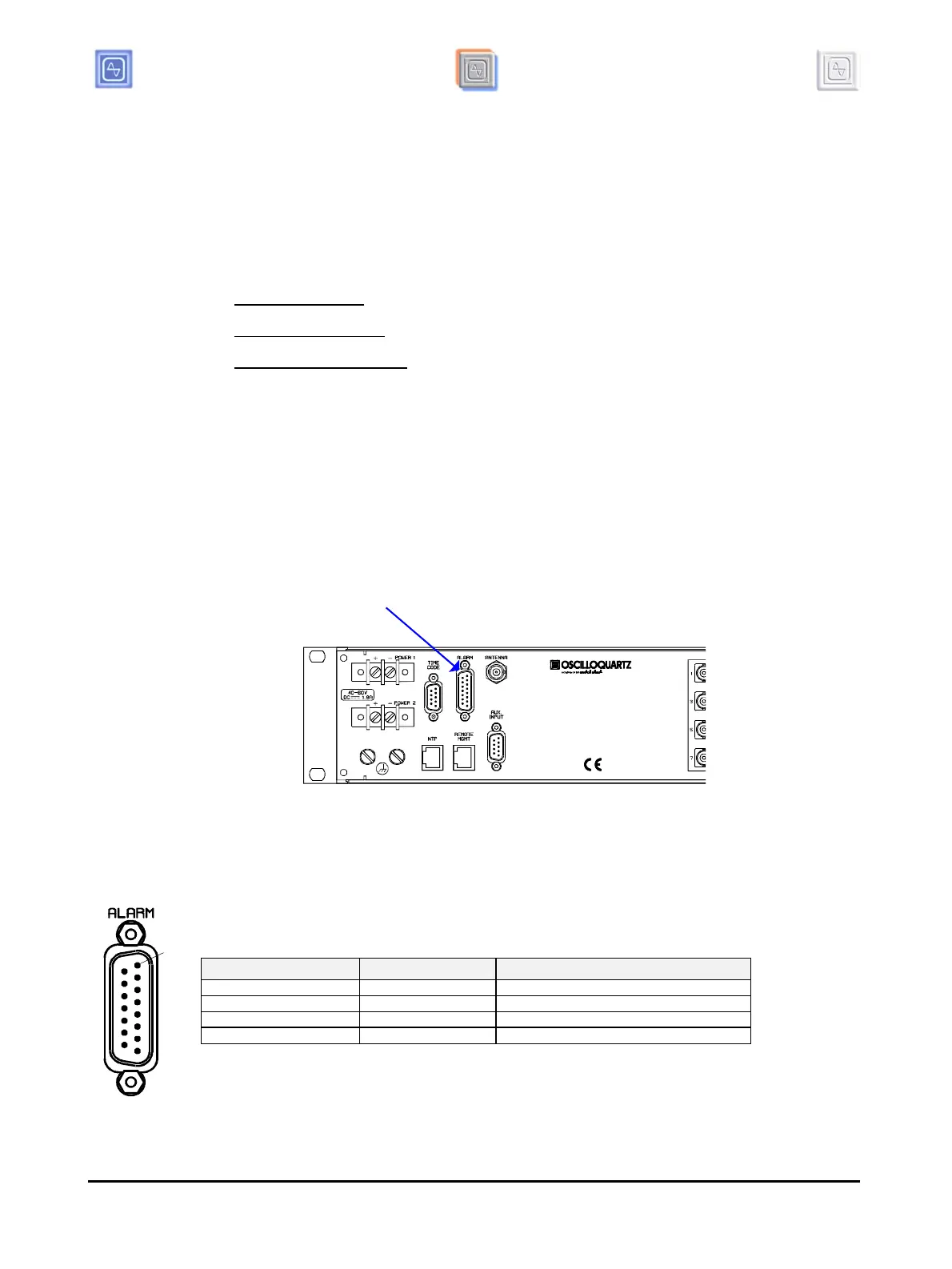
7.2 Electrical Alarm Outputs
The OSA 5240 GPS displays an alarm summary on the front panel and also produces the
associated electrical outputs for remote alarm monitoring. These electrical alarms are
issued from relay isolated contacts and are available on the 'ALARM OUTPUTS'
connector.
DB15: The relays are closed in normal operating state and open in alarm state.
Wire-Wrap: The relays are open in normal operating state and close in alarm state.
Figure 7-1 Alarm Output
7.2.1 "ALARM OUTPUTS" Pin-out
Pin No. Description
Indication
1-9 MINOR alarm Indicates a 'MINOR' alarm condition.
2-10 MAJOR alarm Indicates a 'MAJOR' alarm condition.
3-11 CRITICAL alarm Indicates a 'CRITICAL' alarm condition.
4 to 8, 12 to 15 no connection
Table 7-1 “Alarm output” Pin-out
"ALARM" Outputs
1
 Loading...