Do you have a question about the OSD Audio ISS4 and is the answer not in the manual?
The OSD ISS4, ISS6, and ISS8 are Protected Loudspeaker Switchers, designed to distribute a stereo high-level (amplified) signal into multiple zones. These low-profile speaker selector boxes are an excellent solution for expanding your audio system, allowing you to connect multiple pairs of loudspeakers to a single amplifier or receiver while maintaining a safe impedance level.
The primary function of the ISS series is to enable the connection and selection of multiple loudspeaker pairs from a single amplifier. This allows users to enjoy audio in different rooms or zones of their home or business. Each model (ISS4, ISS6, ISS8) corresponds to the number of speaker pairs it can manage: four, six, or eight, respectively.
A key feature of these devices is their integrated impedance protection circuit. This circuit is manually activated and designed to prevent the impedance presented to your receiver or amplifier from dropping below an unsafe level, typically 5 Ohms. Maintaining a safe impedance is crucial for protecting your amplifier from damage due to overheating or excessive current draw. This protection is effective regardless of the number of speakers connected or their individual impedance ratings.
The impedance protection circuit can also be turned OFF. This option is useful in systems where impedance-matching volume controls are already in place, allowing you to bypass the selector's internal protection and potentially get more power out of your amplifier. However, if you are unsure about disabling this feature, it is strongly recommended to consult a professional contractor to avoid potential damage to your equipment.
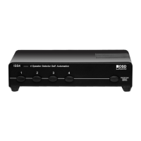
The front panel of the ISS series features clearly labeled "Zone Buttons" (1 through 8, depending on the model). Pressing one of these buttons engages the corresponding loudspeaker pair, allowing audio to be played in that zone. The buttons provide a tactile indication of which zones are active.
On the front panel, there is also a "PROTECTING CIRCUIT SWITCH" which is labeled "Single Pair Direct Switch" or "Loudspeaker OFF/ON." This switch allows you to engage or disengage the impedance protection circuit. When the protection circuit is ON, it ensures a safe impedance load for your amplifier. When OFF, it bypasses this protection, which can be beneficial in systems with external impedance matching.
The rear panel of the speaker selector features clearly marked terminals for connecting your amplifier and individual loudspeaker pairs. There are dedicated input terminals for the L (left) and R (right) loudspeaker outputs from your receiver or amplifier. These inputs are designed to handle up to 100 watts MAX. For each loudspeaker pair, there are corresponding output terminals, ensuring proper connection to the desired loudspeakers. The terminals are designed to accommodate various wire gauges, making installation flexible.
The ISS series is designed for durability and minimal maintenance. However, proper placement is essential for its longevity. Never place the speaker selector in locations exposed to excessive moisture or heat, as these conditions can damage the internal components. To ensure adequate heat dissipation, leave at least 1 inch of space around the unit. This allows for proper airflow and prevents overheating, which can extend the lifespan of the device.
The robust construction and straightforward design of the ISS series mean that once properly installed, it requires little ongoing maintenance. The push-pin terminals provide secure connections that are easy to inspect and re-establish if needed. The manual activation of the impedance protection circuit gives users direct control over a critical safety feature, ensuring the long-term health of their amplifier.
| Type | Speaker Selector |
|---|---|
| Channels | 4 |
| Impedance Protection | Yes |
| Impedance | 4-16 Ohms |
| Material | Metal |
| Dimensions | 2.375" H x 8.5" W x 6" D |