ISS4, ISS6,
ISSB
Speaker Selectors
Thank you
for
giving OSD AUDIO the chance to win your business! We are confident you will find that OSD offers
an outstanding combination
of
performance and value in everything we make.
To
ensure you
get
the most out
of
your new amplifier, please take a moment to read this manual before you
get
started.
Features
INPUT
4
OUTPUT
3
2
OUTPUT
1
I
R+
R· l ·
L+
I
I
R+
R,
L,
L+
IR+
R,
L,
L+
I
IR+
R•
l·
L+
I
R+
R-
l ·
L+
I
liaaaall
11
E3E3E3E3E3E3BB
I I
11
E3E3E3E3E3E3BB
I I
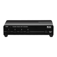
The OSD ISS4, ISS6 and ISSB are low-profile speaker selector boxes that allow you to distribute a stereo high-
level (amplified) signal into multiple zones. All models include a manually activated impedance protection circuit
that can be turned ON to prevent the impedance presented to your receiver from dropping below an unsafe level
of
5 Ohm, regardless
of
the number and impedance ratings
of
your speakers. The protecting switch can also be
turned
off
when used as part
of
a planned system
of
impedance matching volume controls, allowing you to
get
most out
of
your amplifier.
If
you are unsure, consult a professional contractor.
Connecting
your
OSD Speaker Selector
The terminals on the r
ear
of
the speaker selector will accommodate up to 14 gauge cable which will suffice
for
even long connections (greater than 100 Feet
of
wire). For shorter distances, 16-
or
18-gauge wire will suffice. For
behind-the wall installations, we recommend using UL Class 3 approved cable (marked "CL3") for compliance with
local building codes. When connecting a speaker and amplifier, it is important to retain the correct polarity.
To
do
this, be sure that the wire attached to
the+
. red . or positive terminal on the speaker connects to
the+
. red,
or
positive terminal on the rear
of
the selector box. Similarly, the -, black, or negative terminal on the speaker must
connect to the respective
-,
black,
or
negative terminal on the selector box. Polarity should also be maintained
when connecting your amplifiers output to the amplifier on the selector box.
Connecting Speaker Cables
1.
Route the speaker cables from the amplifier and from each speaker zone to the speaker
selector.
2. Strip 3/8" insulation from the end of the cable and twist the exposed end to avoid fraying.
3.
Press
on
a "push-pin" terminal to reveal an eye into which the twisted cable is inserted;
release the terminal to lock
Specifications
ISS4 ISS6
Listening Zones
4 6
ISS8
8
......
3/8"
Protection Circuit High Power Resistors
2 x 10 ohm/15 watt per cha
nn
el 2 x 10 ohm/15 watt per channel
3 x
10
ohm/15 watt per channel
Power Handling with Protection Circuit ON
70 watts/channel
70 watts/channel 100 watts/channel
Power Handling with Protection Circuit OFF
140 watts/channel 140 watts/channel
200 watts/channel
Dimensions: H x W x D
216x112x49mm
433 x
112
x 49
mm
433x112x49mm
8.5" X
4.4
" X l
.93"
l
7"
x 4.4" x l .93"
17"
X
4.4
" X l .93"
Never place a speaker selector where it is exposed to excessisve moisture or heat. Leave at least 1"
of
space above the unit for heat dissipation.
O5D
Audio•
775
Columbia
St•
Brea•
CA•
92821 • www.osdaudio.com • Tel (562) 697-2600 •
Fax
(562) 697-2668
 Loading...