Sheet No.
Issue Date: Rev. C, April 3, 2019
© Bosch Automotive Service Solutions Inc.
14" Clutch Installation
1. Sparingly apply lubricant to the area of the input shaft shown in Figure 1.
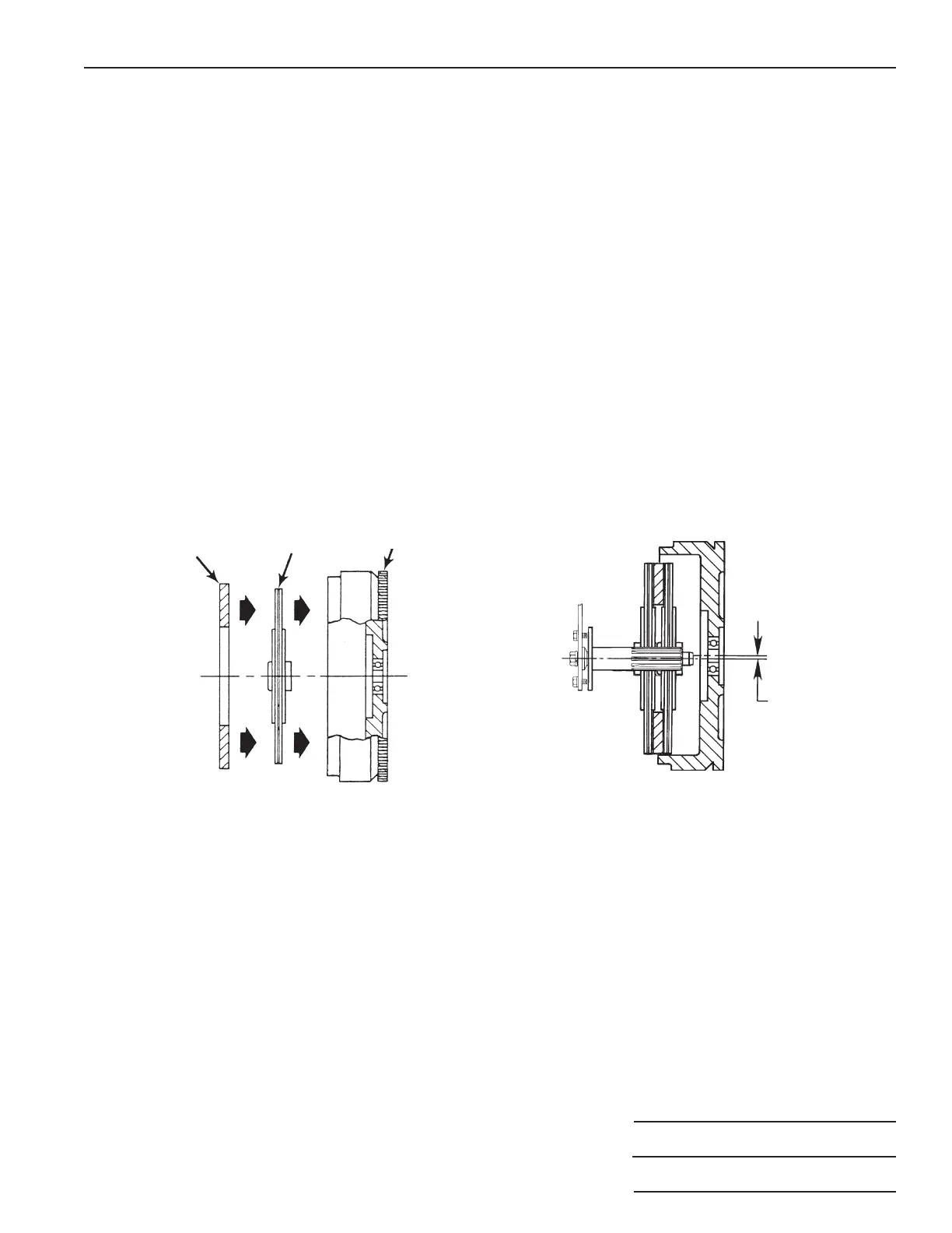
2. Place the new front clutch disc and intermediate plate into the pot type flywheel. See Figure 5.
3. Load the pressure plate and new rear disc on the clutch handler spline shaft.
4. If there isn't enough clearance to roll the clutch handler under the vehicle, raise the vehicle's front end. Position the
clutch handler under the vehicle.
5. Use the adjusting screw to change the angle of the clutch assembly to match the flywheel. See Figure 4.
6. Operate the jack to raise the upper lift arm to the correct height to engage the front disc spline. Roll the clutch handler
forward to insert the spline shaft. Turn the large center cap screw clockwise to rotate the spline shaft for correct
engagement of the clutch disc. Note: The front clutch disc in the flywheel is slightly lower than the center line
of the pilot bearing. It may be necessary to raise the upper lift arm to correctly align the spline shaft with
the pilot bearing. See Figure 6.
7. Bolt the clutch to the flywheel.
8. Slightly release pressure of the upper lift arm. Note: If it is difficult to remove the clutch handler from the clutch
assembly, adjust the alignment of the input shaft by using the adjusting screw.
9. Back the handler away and slowly release pressure to lower the upper lift arm to floor level.
Parts List & Operating Instructions Form No. 545622
3 of 3
Figure 5
Intermediate
Plate
Front
Disc
Flywheel
Figure 6
Raise lift arm
and clutch
assembly to align
spline shaft with
pilot bearing.
 Loading...