Parts List & Operating Instructions
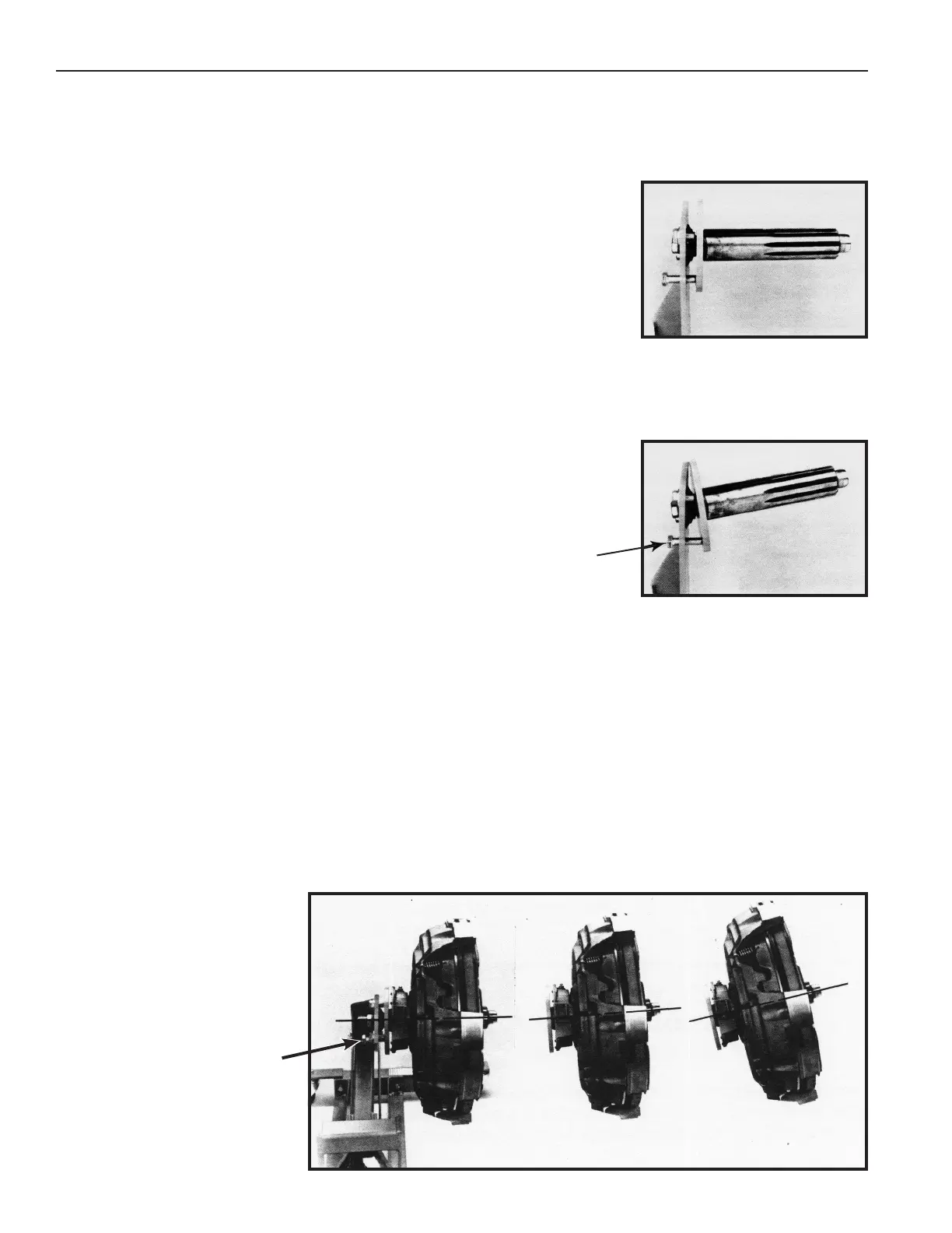
Adjusting
Screw
Figure 4
Operating Instructions
1. Attach the correct splined input shaft (2" or the optional 1-3/4" diameter)
to the clutch handler.
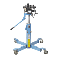
2. Sparingly apply lubricant to the area of the splined input shaft shown in
Figure 1.
3. If there isn't enough clearance to roll the clutch handler under the vehicle,
raise the vehicle's front end. Position the clutch handler under the vehicle.
4. Use the adjusting screw to change the angle of the input shaft so it matches
the angle of the vehicle clutch assembly. See Figures 2 and 3.
5. Remove the jack handle from the holder and insert it into the jack. Operate
the jack to raise the upper lift arm to the correct height, and insert the input
shaft into the clutch assembly. Turn the large center cap screw clockwise
to rotate the spline shaft and engage the clutch discs. If necessary, use
the adjusting screw to further improve the alignment of the input shaft. The
splines must completely engage the clutch assembly before you remove
the clutch assembly.
6. Remove the mounting bolts on the pressure plate.
7. Pull the clutch handler and clutch assembly away from the flywheel.
8. Slowly release pressure to lower the clutch assembly to the floor, keeping
clear of the clutch handler's pinch points as it closes.
Clutch Removal
Form No. 545622, Sheet 2 of 3, Back
15-1/2" Clutch Installation
1. Sparingly apply lubricant to the area of the input shaft shown in Figure 1.
2. Position the pressure plate, clutch, discs, and spacer onto the clutch handler's input shaft. Important: The input
shaft must pass completely through all components of the clutch assembly.
3. If there isn't enough clearance to roll the clutch handler under the vehicle, raise the vehicle's front end. Position the
clutch handler under the vehicle.
4. Use the adjusting screw to change the angle of the clutch assembly to match the flywheel. See Figure 4.
5. Operate the jack to raise the upper lift arm to the correct height. Roll the clutch handler forward to insert the input
shaft pilot into the flywheel pilot bearing.
6. Bolt the clutch to the flywheel.
7. Slightly release pressure of the upper lift arm. Note: If it is difficult to remove the clutch handler from the clutch
assembly, adjust the alignment of the input shaft by using the adjusting screw.
8. Back the handler away and
slowly release pressure to lower
the upper lift arm to floor level.
Figure 2
Figure 3
Adjusting
Screw
 Loading...