Sheet No.
Issue Date: Rev. C, April 3, 2019
© Bosch Automotive Service Solutions Inc.
Parts List & Operating Instructions Form No. 545622
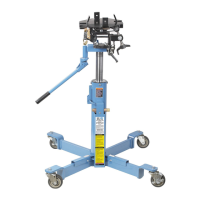
Safety Precautions
CAUTION: To prevent personal injury and/or damage to the equipment,
• Study, understand, and follow all instructions before operating this clutch handler.
• Wear eye protection that meets ANSI Z87.1 and OSHA standards.
• Wear steel-toe shoes that meet ANSI Z41 and OSHA standards.
• If the operator cannot read English, operating instructions and safety precautions
must be read and discussed in the operator’s native language.
– Si el operador no puede leer inglés, las instrucciones de operación y las
precauciones de seguridad deberán leerse y comentarse en el idioma nativo del
operador.
– Si l'utilisateur ne peut lire l'anglais, les instructions et les consignes de sécurité
doivent lui être expliquées dans sa langue maternelle.
• Inspect the clutch handler before each use. Do not use the clutch handler if damaged,
altered, or in poor condition.
• Never exceed the rated lifting capacity of the clutch handler.
• Never move the clutch handler with the load any higher off the ground than necessary.
• Use clutch handler on a hard, level surface.
• Move the clutch handler cautiously around corners to avoid tipping.
• Lowering the lift arm too quickly could cause equipment damage. SLOWLY turn the
hydraulic control valve counterclockwise to release hydraulic pressure.
• Use only those adapters and replacement parts provided by the manufacturer.
• Never modify the unit or adapters.
• Stay clear of the clutch handler’s pinch points as you raise and lower the lift arm.
• Use only approved hydraulic fluid.
Assembly Instructions
(Item numbers refer to the parts list illustration.)
1. Bolt legs (Item #3) to handler using three cap screws (#26),
one threaded handle holder (#29), four washers (#27), and
nuts (#28).
2. Bolt swivel casters (#35) to legs using four washers (#2)
and nuts (#1).
3. Thread two cap screws (#14) through upper lift arm and
tighten.
4. Thread adjusting screw (#5) into upper lift arm.
5. Free up swivel bearing in upper lift arm by applying a
penetrating lubricant to race and working bearing up and
down and side-to-side with a punch or screwdriver.
6. Insert one cap screw (#17) with washer (#18) through swivel
bearing in upper lift arm. Slide plate (#15) over cap screw.
Thread splined shaft (#16) onto cap screw and tighten.
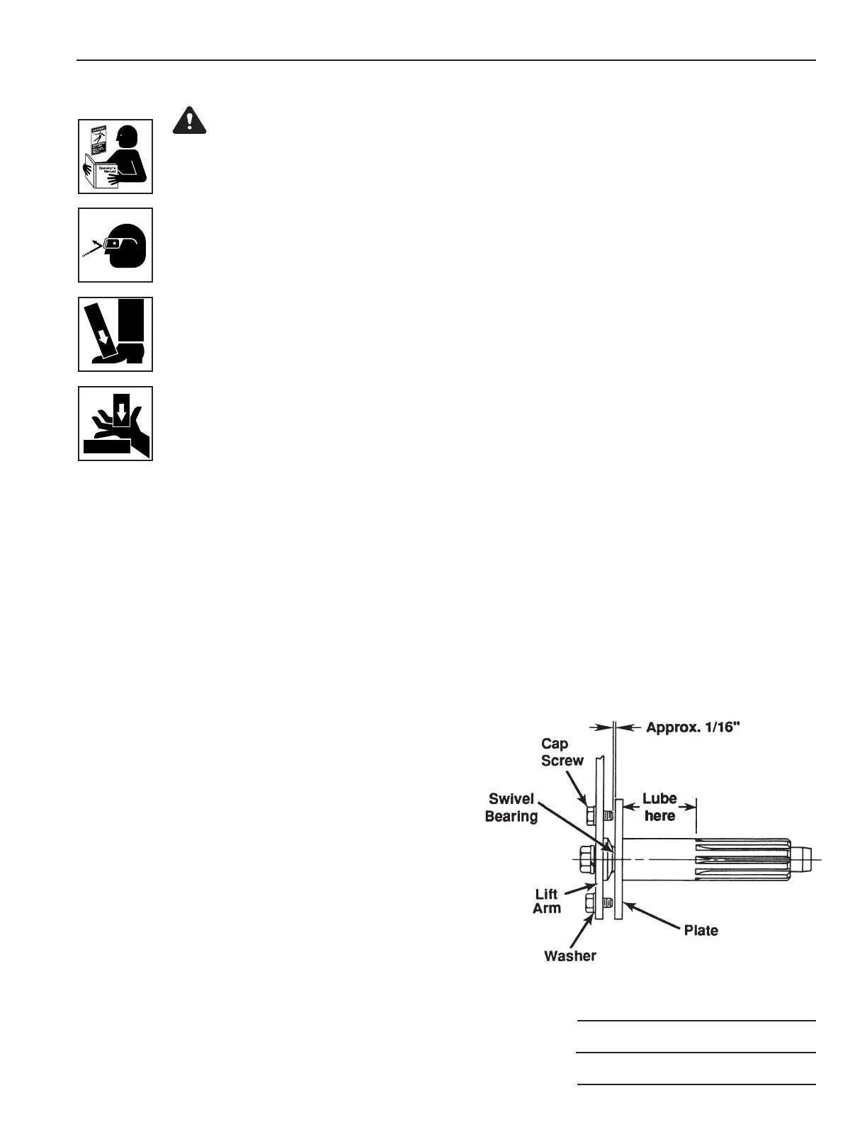
7. Measure distance between plate (#15) and cap screws
(#14). If distance is less than 1/16", remove two cap screws
(#14), and insert a washer (#7) between each cap screw
(#14) and upper lift arm. Wrench tighten. See Figure 1.
Figure 1
2 of 3
 Loading...